


Is GD&T included in the designs of component parts?
The system’s place in fixturing

Opla/E+/Getty Images
It has been said that geometric dimensioning and tolerancing (GD&T) is a contract with inspection but a really good suggestion for production. The basis for this is that when parts are inspected according to their GD&T, the datum features that establish the coordinate system for part inspection are specified in the design. They are a very specific instruction set for the metrologist or inspector.
Sometimes, a poor selection for the datums results in the tail wagging the dog; an inexperienced designer picks datum features that are easy for design, resulting in measurements being made relative to meaningless surfaces and edges. Actually, what should happen is the designer shares an understanding with a fixture designer to select a set of datum features that indicate how the part will be held in both the fixture and in the next assembly/weldment. It makes no sense for a component that is located by a hole and slot to be inspected relative to its edges.
A weld or assembly fixture can be thought of as a set of locators (datum simulators, in GD&T speak) for each component to hold them all in the single, correct relationship. Some of the locators are built into the fixture, while others are features of parts already placed in the fixture. Loading sequence matters, and sometimes it’s critical.
The features critical to part fit-up in the fixture are the features setting up part inspection. Parts that won’t fit are first revealed at inspection, and the reasons they won’t fit can be addressed there rather than production. Instead of being inspected only for “part to print,” parts will be inspected for “part fit and function.”
The most important feature relationships are those among the datum features. Typically, this involves the flatness of a base feature, the angularity of a second feature (relative to the plane established by the base), and the angularity of a third feature to both established planes. For some parts, no feature characteristics other than the qualifications of the datum features require inspection.
A note of caution: Nondatum features used to locate parts in a fixture must be specifically toleranced and should be inspected. Using a feature to locate a part suddenly makes that feature critical, even if the designer only saw it as a “parent” holding other, much more important features in the correct relationship.
Flexible Parts
Which are better, flexible parts or those that won’t flex at all under clamp loads? Ideally, clamp loads will not distort parts being clamped and can sometimes be applied to push flexible parts into place.
As one could say: “Is there anything wrong with parts that just fit?”
Weldment (Assembly) GD&T
While we’re talking GD&T, does the weldment drawing place appropriate emphasis on the right assembly features? Consider a frame made of square tube with gussets in the corners and with holes to attach a panel inside the frame. How should these parts be located?
Set aside for now the decision of whether the tube corners are miter or butt joints. Let’s just consider the four mounting holes for the screen.

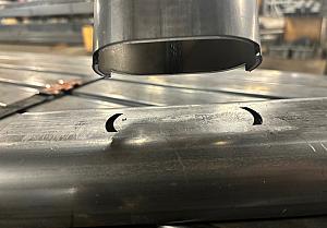
Components are fixtured by height and width of the frame (left), by the location of the holes (center), and by the cut lengths of the tubes (right).
We could clamp the square tubes against fixture pins surrounding the frame, then clamp the gussets into the corners and weld them there (see Figure 1). Alternatively, we could pin the holes down in the fixture and clamp the square tubes to the sides of the gussets. Or, we could locate two perpendicular tubes and clamp everything else against them.
The first method tends to make the frame the right size, the second tends to put the holes in the right pattern, and the third may be the easiest to load. Which is most important? When used correctly, GD&T will tell you.
Using GD&T correctly does not simply mean without violations of applicable rules. GD&T can be on a drawing—and not incorrect— without taking advantage of its ability to express things like These four holes are used to attach a screen with a matching pattern of holes or The size of the outside of the frame is critical for fit and function. It might even say both, which would indicate a need to be very careful with both component dimensions and fixturing.
Consideration should also be given to whichever one is more accurate, your fixture elements or your component dimensions.
3D Printing for Fixture Elements
Many welding tables include a precision grid of holes to locate fixture parts. Exactly what (pin, clamp, angle) goes where is important to document. To take this a step further, 3D printing can be used to create dedicated fixture parts that hold specific components in specific locations; for instance, two stub pins for the weld table on the bottom, a pin or clamp pad in a specific location on the top. These dedicated fixture parts can be stored in minimal space for reuse or reprinted as needed.
Geo-Set and Re-Weld versus Single-Weld Operation
One way to avoid weld distortion is to only tack parts together while they are in the fixture. After the weldment geometry is set by tacking, the weldment can be removed and the welds completed. This geo-set and re-weld process often allows easier access to backside welds and may be necessary to avoid damaging 3D-printed fixture parts.
Specified weld sequences may also be critical to prevent welds from pulling the parts out of location. Document weld sequences as well as where pins, clamps, and pads are located on welding tables.
There is much to consider in the design and construction of weld or assembly fixtures. GD&T can be used to highlight critical relationships among parts, fixtures, and assemblies.
About the Author
About the Publication

subscribe now

The Welder, formerly known as Practical Welding Today, is a showcase of the real people who make the products we use and work with every day. This magazine has served the welding community in North America well for more than 20 years.
start your free subscription- Stay connected from anywhere

Easily access valuable industry resources now with full access to the digital edition of The Fabricator.

Easily access valuable industry resources now with full access to the digital edition of The Welder.

Easily access valuable industry resources now with full access to the digital edition of The Tube and Pipe Journal.

Easily access valuable industry resources now with full access to the digital edition of The Fabricator en Español.
- Podcasting

Matt Brunner, co-founder and co-owner of Manitowoc, Wis.-based Brunner Fabrication joins us to talk about how he transformed...
- Trending Articles
1
Curious how to get started as a metal sculptor? Established artists share tips

2
Automating the weld grinding process

3
StrataTech Education Group releases fifth season of “Top Welder”

4
Face shields designed for comfortable protection in welding, cutting applications

5
Is GD&T included in the designs of component parts?
