


Defining basic terms in sheet metal bending
Reader questions about V-groove bending, bend allowances, and k-factors

FIGURE 2. This CNC system has multiple cutters that cut V-grooves in sheet metal.
Question: We are attempting to form V-grooved material on our brake, and we are running into an issue with the punch getting pinched by the material as the ram lowers. Is there special tooling we’re supposed to use for bending the V-grooved material?
Answer: The V-grooving method has some unique problems. Before answering your question, allow me to elaborate on V-grooving for any readers unfamiliar with the process.
V-grooving involves cutting along the bend line (see Figure 1). The sheet material is placed and firmly clamped, or sometimes held in place with a vacuum system. A CNC system uses a series of cutter blades that travel down what will become the inside bend line (see Figure 2).
The method aims to create a crisp, sharp inside bend radius, often called for in decorative architectural features. For this goal, it does a great job.
There are some drawbacks, however. First, you are entirely at the mercy of the material and its variations associated with thickness. For example, if you have 16-ga. material, the thickness can range from 0.053 in. to 0.067 in., a variation up to 0.014 in. that can create a corresponding change in the V-groove depth. This leads to variations in the bend angle.
V-grooving also removes material at the bend line, which weakens the bend. This usually isn’t a problem for architectural parts, but it does explain why V-grooving does not work well with thicker materials.
To the best of my knowledge, forming a V-grooved part requires no special tooling, although common sense would lead you to use an acute-profile punch with a very sharp nose radius. You also might consider taking the bending angle only to the point where the part touches the faces of the punch and no further. This helps you avoid pinching or smashing the bend into itself or the toolset, causing “back-breaking” of the bend. This process is typically used in thin materials, and the material is even thinner at the bend line. Finishing the bend by hand should be easy and will likely give you the best results.
Defining the Bend Allowance and Bend Deduction
Question: I’m new to bending and need a little help with some fundamentals. Could you explain the bend deduction and bend allowance in more detail?
Answer: Figure 3 should help answer your question. Note that you have a dimensional value from the edge of the part to the tangent point of the flat and the beginning of the radius, noted in the figure as X1 and Y1. These give you your inside dimension, but they do not account for the material that makes up the bend radius. Now, note the outside dimension, X and Y. They begin at the same edge but this time continue to the apex of the bend.
Calculate the total inside dimension, X1 + Y1. Now, calculate the total outside dimensions, X + Y. There’s quite a bit of dimensional difference between them, yet we still need to arrive at the same flat-blank calculation. Using the bend allowance and bend deduction helps us do this.
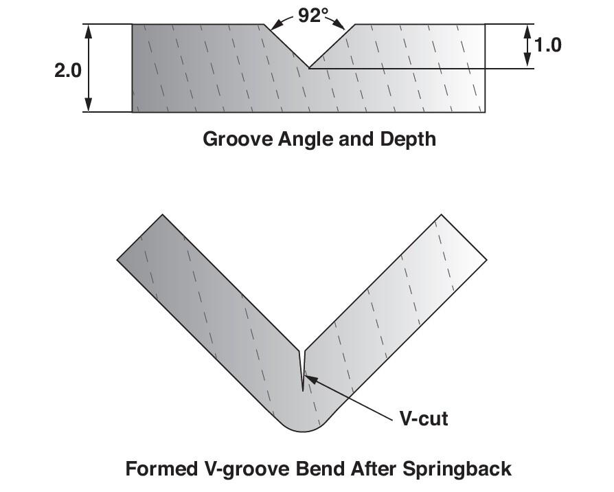
FIGURE 1. V-grooving involves cutting a groove along the bend line. You can compensate for springback by adjusting the angle of the V-groove.
So, how exactly do we apply them? The answer is incorporated into the names, “bend allowance” and “bend deduction.” The bend allowance “allows for” the material included in the radius. We do this by adding the bend allowance to the total inside dimensions (X1 + Y1 in Figure 3). Doing so will give you the required value for the flat pattern. Now, measure the total outside dimension (X + Y in Figure 3). You deduct the bend deduction from the outside dimension total, and you get the same flat blank. The final values should be the same.
(Editor’s Note: For a deeper dive on how to calculate the bend allowance and bend deduction, see “Sheet metal bending calculation basics.”)
Defining the Neutral Axis and K-Factor
Question: We’re having a few debates in our bending department about what some fundamental terms mean, including the neutral axis and k-factor. What exactly are they, and how do they affect the bend?
Answer: When you bend sheet metal, material near the inside radius gets compressed while material near the outside radius expands. The bend’s neutral axis is an area where the material neither expands nor compresses. The neutral axis stays the same length, but it also moves toward the inside of the bend. This causes the bend to elongate the material (see Figure 4).
The k-factor is a multiplier that helps you determine where the neutral axis will be located after forming. That value is then used to calculate the bend allowance.
Pushing the Limits on Tonnage
Question: We just bought a new press brake. Our engineering team is working through updating our programs, and we’re making significant progress. Also, we’ve upgraded from our old planed four-way dies to sectionalized precision-ground tooling.
However, we are facing challenges with bending some of our thicker materials, which are facing some tonnage limitations on our new machine. We used to bend one part on a 3-in. die with no issue on the old press. Now, with the new press, since the tooling has a preset tonnage limit, it errors out on the part. We’ve checked with our machine manufacturer, and they don’t condone anything outside the parameters specified.
We know this is a great safety feature; it prevents the part from damaging the tools and our new press brake. But we consistently bent this part on the old press brake with no issue. Is this just the nature of high precision versus our planed four-way die? Is the planed tooling more forgiving with tonnage?
Answer: You are correct: An abundance of caution is considered when calculating the tonnage ratings for both the tooling and the machine. Put yourself in the machine and tooling manufacturer’s shoes. Imagine a customer calling you after a catastrophic failure saying, “You told me I could do this, and look what happened!” You might even hear the word “lawsuit” in the same sentence.
Following the warranty guidelines is wise. You will know your investment is covered against any possible defects, and your operators will remain safe while working on an undamaged press brake.
This might not apply to your machine or tooling manufacturer, but historically, at least, many tooling manufacturers have an average safety coefficient of around 30%. This means they are rated about 30% under the maximum tonnage load. Even knowing that you conceivably could go 30% more, running anything out to its maximum is not a good practice.
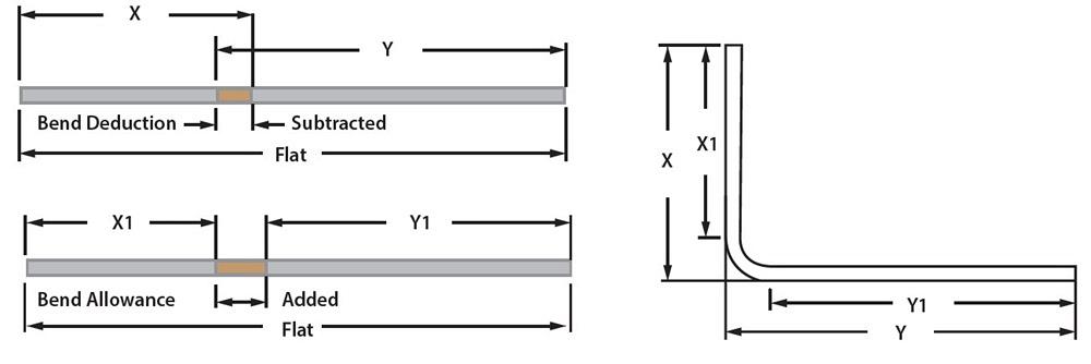
FIGURE 3. This shows how to develop your flat using the bend allowance or bend deduction.
Precision-ground tooling, on average, is hardened to a higher Rockwell number than traditional planer tooling. Therefore, precision-ground tools may be easier to break in some high-tonnage applications.
In the overall scheme of things, be glad you still have the old machine and tooling just for those borderline bends. On the new machine, you do not want to void your warranty. And yes, it’s no secret that plenty of shops see what they can get away with, especially after their press brake warranty expires. You might be willing to take the risk. But trust me here—it’s still not a good idea.

FIGURE 4. The k-factor describes the neutral axis shift during forming, calculated as t/Mt.
subscribe now

The Fabricator is North America's leading magazine for the metal forming and fabricating industry. The magazine delivers the news, technical articles, and case histories that enable fabricators to do their jobs more efficiently. The Fabricator has served the industry since 1970.
start your free subscriptionAbout the Author

About the Publication

- Stay connected from anywhere

Easily access valuable industry resources now with full access to the digital edition of The Fabricator.

Easily access valuable industry resources now with full access to the digital edition of The Welder.

Easily access valuable industry resources now with full access to the digital edition of The Tube and Pipe Journal.

Easily access valuable industry resources now with full access to the digital edition of The Fabricator en Español.
- Podcasting

Max Ceron, the director of the CWB Association, discusses his role in supporting the welding and fabricating industry...


