


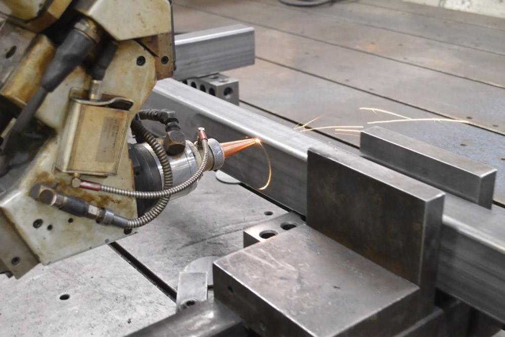
Tube fabricator uses 3D laser for cutting after bending
Fully articulated laser cutting provides precise feature locations, eases fixture concerns
Although metal-cutting lasers are nothing new, their capabilities continue to advance, helping the manufacturing industry to be more capable and more productive than ever before. Equipped with software that becomes easier to use with each generation, loaders and unloaders that move material in and out quickly, and part sorters that segregate parts, they help fabricators to work more efficiently and contribute to the growing role of manufacturing.
In tube fabrication, the lion’s share of laser machines cut straight tube. Using an automated loading system, chucks that grip the tube ends to hold the tube stationary or rotate it, and software that optimizes cutting paths, this variety of machine is dazzling in its efficiency. However, some tube applications require a different sort of machine, one in which the part to be cut sits on a bed. Often this sort of laser doesn’t process parts as quickly as the other variety, for two reasons. First, the part is loaded manually and clamped in place manually. Second, because the tube isn’t gripped with chucks, it doesn’t rotate. Cutting holes, slots, and notches around the tube’s entire circumference means having to cut a few features and then reposition the tube to finish it.
Although they are extremely capable, they aren’t used as commonly as the others. These are niche machines.
“Most of them are in the Detroit area,” said longtime fabricator Lisa Wertzbaugher, sales manager for Superior Tube Products Inc., Davenport, Iowa. “They’re used quite a bit for prototyping work,” she said. Davenport is nowhere near Detroit, Superior has no automotive business, and it doesn’t do much in the way of prototyping, yet the company has three such laser machines. What gives, you ask? The company needs them for many reasons, and more are sure to crop up in the future.
Size and Symmetry
“We run dozens of unique parts through these lasers,” said Nathan Tindall, lead estimator and laser programmer, referring to the machines with 3D cutting capability. “We have more than enough work to keep them running at close to capacity most of the time,” he added.
Two chief criteria are size and symmetry. The company does quite a bit of work to support the agriculture equipment business and other industries that need really large components. It often fabricates workpieces up to 24 inches in diameter and more than 30 feet long. Superior’s two inline tube lasers can handle quite a bit of this work, fabricating rounds up to 16 in. in diameter and squares up to 12 by 12 in., in lengths up to 30 ft. However, because its larger-capacity machines don’t have cabinets that enclose the cutting area—the units are essentially part beds with fully articulating laser heads—they can handle extremely large-diameter tubes of essentially any available length.
Symmetry about the tube’s centerline is another chief issue. The company fabricates parts made from D-shaped tube and other not-so-common profiles. On lasers designed to cut tube inline, the chucks that grip, stabilize, and rotate the tube usually are designed to handle common shapes, such as rounds, squares, and rectangles. So, for D-shaped tubes and other unusual profiles, the company relies on its 3D cutting machines.
Deep Roots in Tube
Superior’s roots in tube fabrication run deep. An interest in tube fabrication, and faith that this would be a lucrative business niche, led Wertzbaugher’s parents, Larry and Gloria Dlouhy, to found the company back in 1991.
“This was primarily a stamping company when my parents purchased it,” Wertzbaugher said. They had a two-step plan in mind: First, buy a manufacturing company; second, change everything about it.
“My father had been a general manager at a sheet metal fabricator and had had a lot of difficulty in procuring bent tube,” Wertzbaugher explained. The company had no problem making sheet metal parts, but it had no expertise or equipment for fabricating tube. If a bid called for an assembly that included bent tube, the company would try to outsource the tube portion of the work, but the Dlouhys struggled to find tube fabricators. Again and again and again. And again.
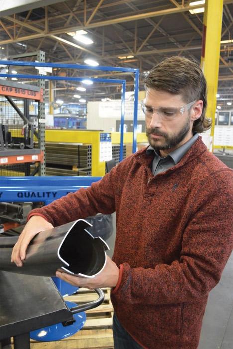
Many parts fabricated at Superior Tube Products Inc. don’t lend themselves to cutting on the company’s inline tube lasers. Unusual profiles and notches in the tube’s end are well-suited to the company’s 3D laser machine.
This wasn’t just opportunity knocking; this was more like opportunity kicking the door down and ripping half the door frame off the wall for good measure. The Dlouhys took notice.
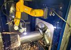
After purchasing the company, they gradually changed its focus to tube fabrication by purchasing fabrication machines and accumulating tube fabrication experience. Although the Dlouhys have since sold the company and retired, the cumulative expertise continues to reinforce and expand Superior's unique market position. While the company does a lot of rotary draw bending, it also does a lot of press bending, CNC machining and drilling, welding (both manual and robotic), and assembly. It develops its own tooling as well, giving the company a lot of control over lead times and product quality.
It would be difficult to develop a better foundation for a company that has built a reputation for solving tricky manufacturing problems.
Laser Cutting Before Bending
Many of the tubes fabricated at Superior have large numbers of holes—in some cases, dozens—and each has a specific purpose and therefore a specific location. Making a large number of holes, notches, piercings, and other features along the tube’s length on an inline tube laser is an easy task, but bending such a tube can be challenging, at best.
“In a case of mandrel bending, we wouldn’t even try to bend such a tube, because the slag inside the tube from the laser process would interfere with the mandrel,” Tindall said.
However, bending without a mandrel isn’t any better. Every tube would have to be loaded into the bender in a consistent and precise orientation to get the bends oriented just right relative to the holes, slots, and notches made by the laser. Considering the tube’s circumference to be a clock, the 12 o’clock position would have to be at high noon every time to keep every hole oriented correctly. Just a bit of rotation would render the tube useless.
By the same token, the tube would need a precise orientation in the first step so that the weld seam would have a consistent location relative to the holes. Because the weld seam is harder than the parent material, any variation in weld seam location would have the potential to cause variations in bending characteristics, leading to slight amounts of dimensional distortion.
Finally, even if everything were to align well, holes in the bend zones would undergo a bit of distortion. Compression along the inboard side of the bend and stretching along the outboard side of the bend would result in a variety of misshapen features.
For the most part, it’s better to bend it first and do the laser processing second.
Fixturing Fits
Another reason for 3D laser cutting concerns fixturing. In many cases, a partially fabricated part is sent to a saw for cutting or to a machining center so holes, notches, and other features can be added. Many of these parts need sturdy, custom-made fixtures to hold them tight, in the right place at the right orientation, for sawing or machining. Drawbacks include the engineering time needed to develop each fixture, the machining time needed to make the fixtures, the floor space eaten up by storing them, and time needed to swap out fixtures when changing from one job to another. Superior fabricates a multitude of such parts that need cutting or part features added after bending, and therefore would need a multitude of fixtures.
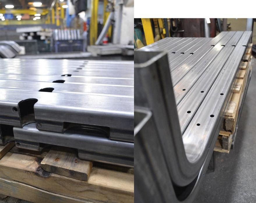
Notches that run through opposing walls, notched corners, and holes are some of the many features Superior makes on its laser machines. Such features aren’t difficult for a laser machine with chucks, but subsequent bending, which stretches the tube along the outside of the bend and compresses it along the inside of the bend, can change feature locations and shapes. Superior finds success in making such parts by bending them first, then cutting the features on 3D laser machine.
A laser plays by a different set of rules. A laser usually does a comparable job more quickly and, because laser cutting is a noncontact process, it doesn’t need a rugged fixture. It just needs a clamp to secure the part in place.
- Parts that are difficult to fixture for sawing or machining fall into a few categories.
- Extra grip length. Often the raw material length exceeds the finished part length. For example, some parts need additional grip length so the bender can do its job; the additional length is later cut off.
- Complex geometries. For complex parts, such as tubes that have compound bends, using a saw to trim the ends would be impossible without a custom-built fixture.
- Simple geometries. A tube with just a few gentle bends—think of the distinctive horns on Texas Longhorn cattle—can be challenging to fixture. With a lot of length along the X axis and little along the Y axis, this geometry is prone to twisting in the fixture under the pressure imparted by a saw blade or the machining tool’s head. If the short leg doesn’t have much length, the fixture can’t grip it securely.
Another consideration is the portion removed from the workpiece. In most cases this is merely scrap, but not always. Once in a while, the excess material trimmed from a part is substantial and can be used to manufacture another part. Although it’s uncommon that a short length of tube would be suitable for reuse, Superior does some work in stamping to round out its portfolio of capabilities, and it determined that the excess trimmed from one particular stamped part was large enough to be a viable feedstock for another part. Superior went so far as to collaborate with the original equipment manufacturer (OEM) to modify the original part to optimize the trimmed piece for making the second part, Tindall said.
Making Good Parts with Bad Fit-up
Assembling a machine with thousands of parts is no small feat. All of the parts aren’t interdependent, of course—for example, an automobile’s front bumper and rear bumper don’t interact with each other—but still, to some extent, each of these can be located relative to the other. The same goes for every component on every assembly in every manufactured item; each has a specific location and must be manufactured to the correct dimensions so it will fit and function the way it was intended. Even if the component is essentially a stand-alone item and doesn’t have a complex function, making it correctly means it will fit correctly. Unless it doesn’t.
“We had a case in which we made a part to spec—every dimension was right on—but still it didn’t fit into the assembly like it was supposed to,” Tindall said. “All of the dimensions were good, but the welder couldn’t get it into position to weld it.”
During a visit to the OEM, careful measurements revealed that the component Superior provided, and the assembly it was supposed to fit into, were made in accordance with their respective prints. When a good part doesn’t fit into a good assembly, a little more detective work is in order.
On a complex assembly, measurements, dimensions, and locations can be tricky things. Even something as simple as a tube with just one bend and a few holes can become expensive or difficult to produce if the engineer or designer denotes dimensions or tolerances that aren’t realistic, such as tube with zero ovality, bend locations based on tangents derived from straight sections, or long parts with specific bend angles and precise end locations.
As the number of holes, notches, and other features multiplies, the challenges in annotating proper locations also multiply. Locating several features along a common centerline is easy to do, but rarely do features line up on something as simple as a centerline. Without a simple reference point, locating one feature relative to another can be a complicated matter prone to errors.
“Most parts have lots of possible reference points, so the engineer just has to pick one,” Wertzbaugher said. He might pick a feature near another as a datum, but near doesn’t mean easy to use. It gets even trickier when several people contribute to a project. A dimension that is too tight or an interference that is overlooked can make an assembly impossible to build.
It turned out that the error was on the print provided to Superior, so Superior changed a hole location so the part would fit. Of course the solution was easy to implement—it was just a matter of updating the program and pressing START on the laser.
About the Author

About the Publication

subscribe now

The Tube and Pipe Journal became the first magazine dedicated to serving the metal tube and pipe industry in 1990. Today, it remains the only North American publication devoted to this industry, and it has become the most trusted source of information for tube and pipe professionals.
start your free subscription- Stay connected from anywhere

Easily access valuable industry resources now with full access to the digital edition of The Fabricator.

Easily access valuable industry resources now with full access to the digital edition of The Welder.

Easily access valuable industry resources now with full access to the digital edition of The Tube and Pipe Journal.

Easily access valuable industry resources now with full access to the digital edition of The Fabricator en Español.
- Podcasting

Patrick Brunken, VP of Addison Machine Engineering, joins The Fabricator Podcast to talk about the tube and pipe...
- Trending Articles
1
Zekelman Industries to invest $120 million in Arkansas expansion

2
Making the move from hard automation to robotic welding
3
Brushless copper tubing cutter adjusts to ODs up to 2-1/8 in.

4
HGG Profiling Equipment names area sales manager

5
Miscellaneous metals fabricator increases productivity and opportunity with plasma cutting