


Contributing Writer
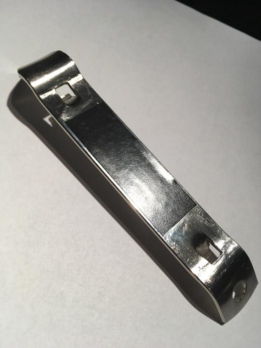
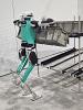
Figure 1a
We have a need for a 3D CAD model of this bottle opener. Note that the lanced hooks cut through adjacent bends.
Editor's Note: If you would like to download the 3-D CAD files associated with this column, click here.
When designing an enclosure, it is useful to have accurate models for sizing and planning. Sometimes “reverse engineering” is required.
For a recent project I needed a bottle opener. Figure 1a is a photo of an example item. Note that the lanced hooks cut into adjacent bends because of the sequence of hits in a progressive stamping die.
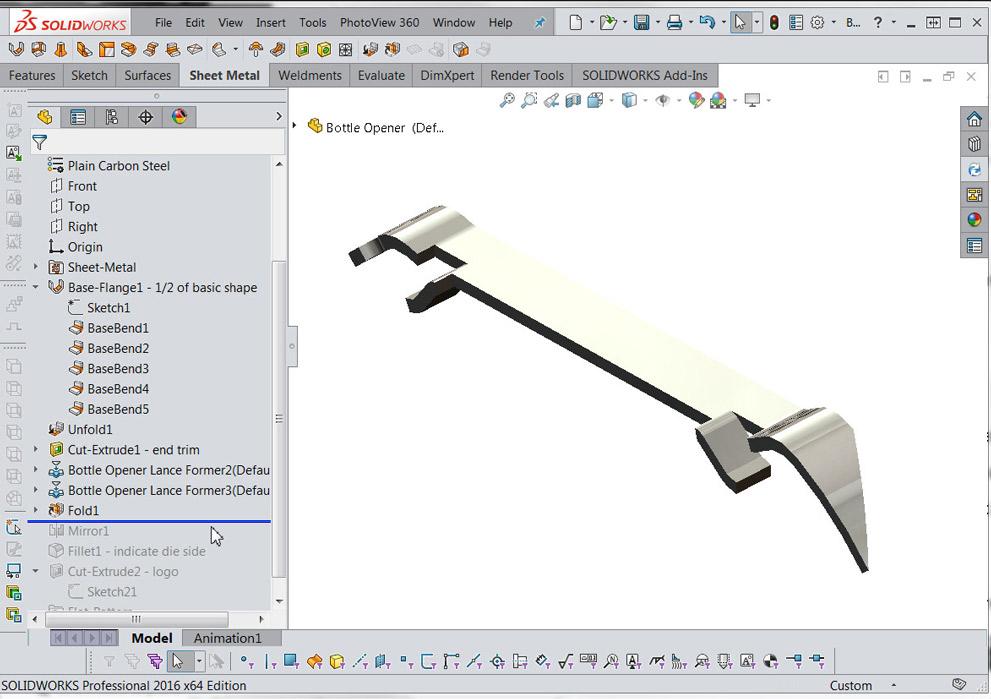
A 3D CAD version of this item is shown in Figure 1b. It is a reasonably good visual copy. Dimensionally speaking, it is what I measured with hand-held calipers—probably within 0.004 inch, but no guarantees.
The following review of the CAD techniques used mentions software-specific terms such as sheet metal, forming tool, unfolding, and mirroring. For planning how to model this, the design intent, or guiding light, is to create a model suitable for appearance in a photorealistic rendering. As always, speed matters. We are on the clock. This item is merely a prop for visualization.
Given my CAD skill set, I frequently use sheet metal modeling tools in CAD. The speedy technique is sheet metal-oriented. An artifact of this technique is that the model can be unfolded. In other words, it is nearly suitable for designing a progressive stamping die. However, manufacturing bottle openers is not the intent.
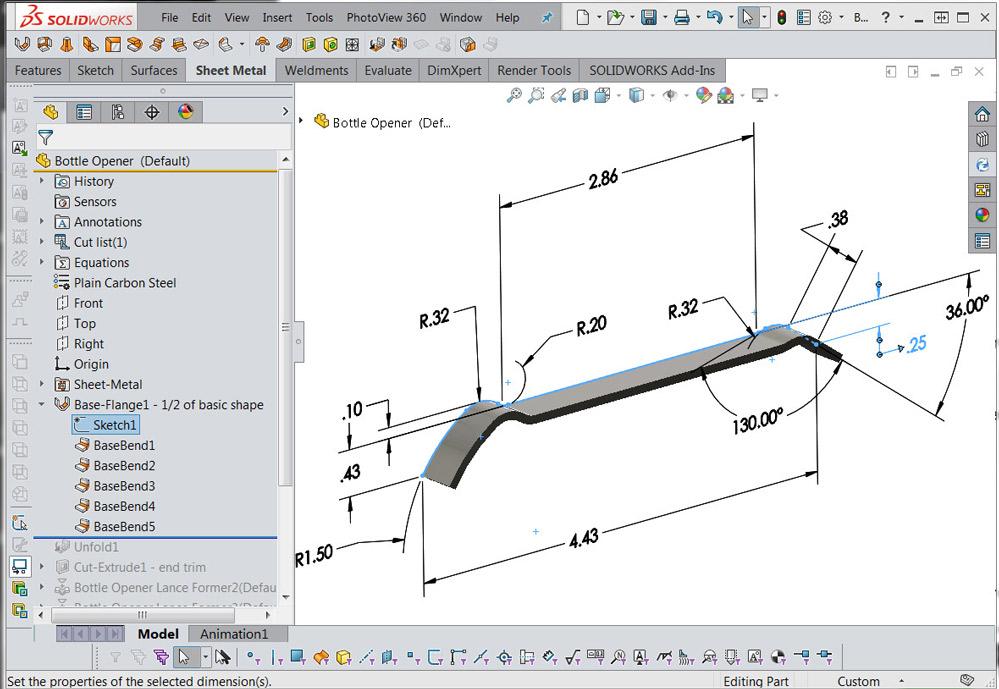
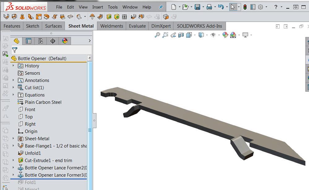
This model starts with a sketch, shown in Figure 2a. The sketch line drawn is merely an imaginary edge. That sketch is subsequently used to create a sheet metal base flange. This is only half of the model. It will be mirrored later to complete the width.
The Mirror feature was used in the spirit of speedy CAD. Why model two identical edges if they are symmetrical? Model one and mirror it. That “goof-proofs” the symmetry and sort of speeds the CAD.
According to the rules of CAD, the sequence of modeling matters. A Base Flange > Unfold > Lance > Fold sequence allows the lances to exist before the base bends. If the forming tool is applied to the opener in the bent state, the lance will not cut into the adjacent bend.
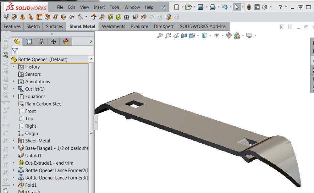
The Forming Tool is a versatile modeling resource. In this example, a Forming Tool feature is used to add lances. As shown in Figure 2b, the lances mimic the appearance of the actual part. By the way, according to the rules of CAD, the Forming Tool feature must create normal edges in the sheet metal model. In Figure 2c the lanced tabs extend past the midpoint of the model. These unneeded artifacts from the Forming Tool will disappear when the part is mirrored (see Figure 2d).
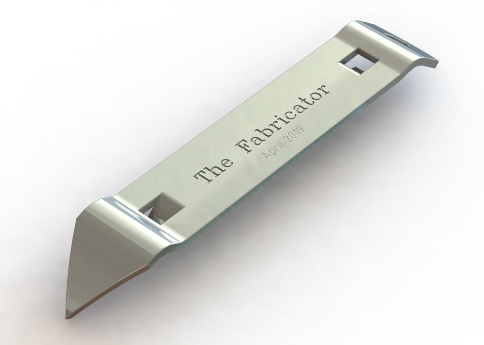
Figure 1b
With 3D CAD, we have reverse-engineered the opener from Figure 1a. Only the name has changed to protect the innocent
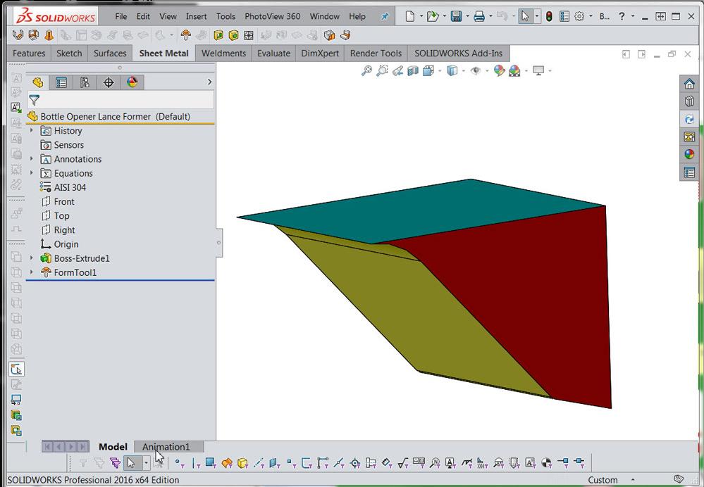
A side note about Forming Tools. A Forming Tool is a separate CAD model that resides in a folder tagged as a Forming Tools Folder. As shown in Figure 3a, colors on its faces indicate stopping face, cutting face, or forming face. Note: CAD tools are available that help with the creation of colorful Forming Tool models.
The machinists amongst us are wondering about speedy modeling and all of that. Speedy CAD and Forming Tools meet when the feature, in this case a lance, appears more than once—in this case only twice (or in several models, should this turn into a line of can opener products). Drag-and-drop is all it takes to apply the Forming Tool into the sheet metal part. Well, positioning after dropping is required too.
Forming Tool features can be linked to the Forming Tool model. With centralized editing, changes can be streamlined. If all of the lances need to change, then simply edit the Forming Tool model, rebuild the Forming Tool features, and voila. All lances are updated perfectly.
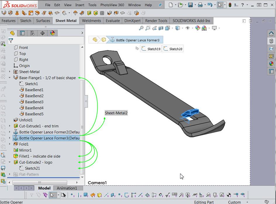
To complete the model as shown in Figure 3b, filleted edges create roundness to indicate the die side/burr side from stamping. Rather than model burrs, the cutting edge of the tool was simply left razor-sharp. The thought of modeling burrs may see preposterous, but we did take time to model the lance cuts nicely, eh?
When the goal is photorealism or virtual prototyping, little details might matter. We might be modeling for virtual reality.
Gerald would love for you to send him your comments and questions. You are not alone, and the problems you face often are shared by others. Share the grief, and perhaps we will all share in the joy of finding answers. Please send your questions and comments to dand@thefabricator.com.


The Fabricator is North America's leading magazine for the metal forming and fabricating industry. The magazine delivers the news, technical articles, and case histories that enable fabricators to do their jobs more efficiently. The Fabricator has served the industry since 1970.
start your free subscription
Easily access valuable industry resources now with full access to the digital edition of The Fabricator.

Easily access valuable industry resources now with full access to the digital edition of The Welder.

Easily access valuable industry resources now with full access to the digital edition of The Tube and Pipe Journal.

Easily access valuable industry resources now with full access to the digital edition of The Fabricator en Español.
Patrick Brunken, VP of Addison Machine Engineering, joins The Fabricator Podcast to talk about the tube and pipe...


