Contributing Writer
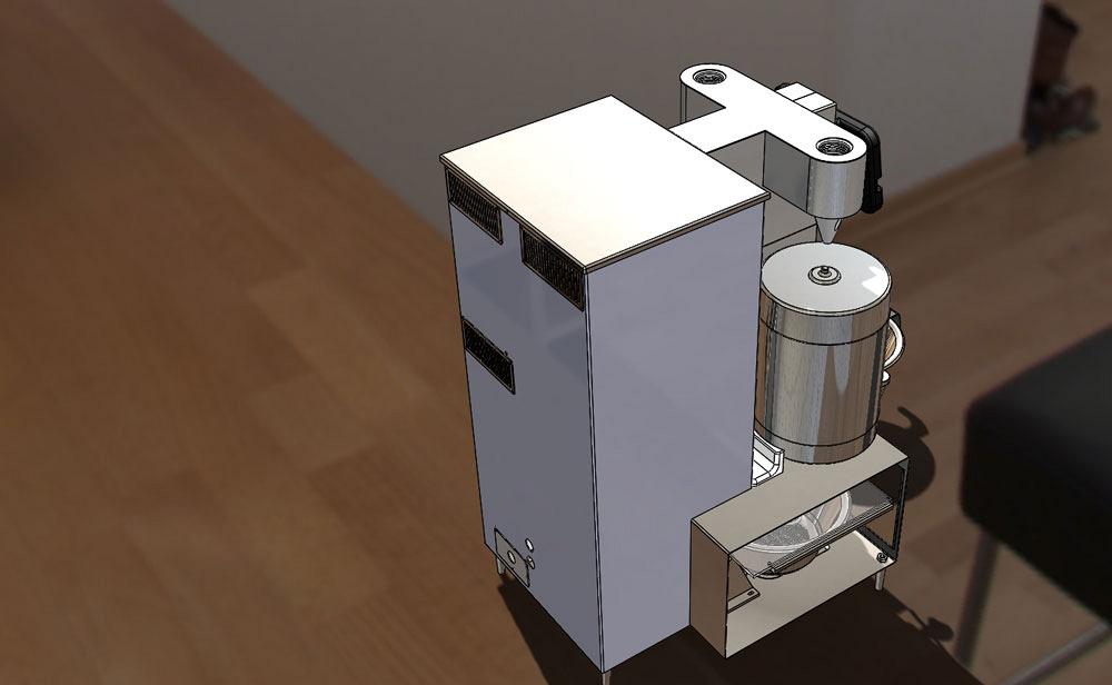
Figure 1
This CAD model of the coffee maker is roughly what the industrial designers asked for. The prototype was an amazing apparatus. It was not quite beautiful, but certainly exotic. With enough welding and grinding, multiseam designs like this can be fabricated in small batches. However, an immediate DFM goal was to reduce cost.
Disclaimer: This case study of a coffee maker’s sheet metal cabinet features a pair of inventors doing their best without the benefit of manufacturing experience. The result was an award-winning product design in 2018. Over several years, they gained experience in our trade, sometimes painfully. It is very brave of them to share this with us.
Even though the author’s explorations in design for manufacturability (DFM) were a bit off the mark as related here, they are presented as an example of the kind of effort that goes into a DFM project, particularly one involving an industrial design (ID) team that is committed to a vision.
In the previous edition of this column (“A 3-D CAD modeling case study: Using the prototype to develop a design for production,” Precision Matters, The FABRICATOR®, August 2018, p. 46), the ID team’s vision was not part of the DFM team’s thought process. The DFM team extensively modified the ID team’s prototype design, shown in Figure 1a, to reduce cost and improve function. They proudly presented the work shown in Figure 1b, and they got raspberries in return.
This edition relates another aspect of DFM: negotiation with ID. As internal detail is added to the DFM team’s 3-D computer-aided design (CAD) model, the external details are almost certain to change.
Constraints are like barriers in a maze. If you know them, they don’t slow you down a bit. If you ignore them, you’re likely to bang your head against the wall.
Here’s a tip: Try to avoid having constraints emerge during the design process. Instead, collect the constraints in a hoard while inventing the invention, and then present the entire collection to the design teams as a starting gift.
During the review meeting of the DFM team’s Version 1 model, as shown in Figure 1a, many of the internal details of the coffee maker were discussed. For example, while the chemistry of the patented brewer operation was a success in the prototype form, that physical apparatus was not modeled in 3-D CAD. It is hidden in Figure 1b, but it’s in there now. Examination and discussion of that internal detail helped focus the meeting on what the shape needed to be instead of why it used to be different.
It has been my experience that both DFM and ID contributors are very studious and thoughtful about their work. Neither team reacts well when change is imposed or an idea is rejected out of hand. The ability to quickly modify 3-D models during review helps to relieve stress, both in the model and in the crew.
Here’s another tip: Keep these concept models simple and easy for you to change on the fly. Parametric links are useful at this stage in modeling.
While planning the internal layout and preparing Figure 1b, the DFM team tried to anticipate the future in terms of supply chain/compliance, sequence of assembly, service access, and end-user experience. The emerging internal details, along with better clarity on external constraints, required changes to the shape of the supporting framework and related cover system. If the ID team had started with accurate representations of constraints, such as component sizes and access points, much of the expense and time related getting the Version 1 model to Version 2 could have been avoided.
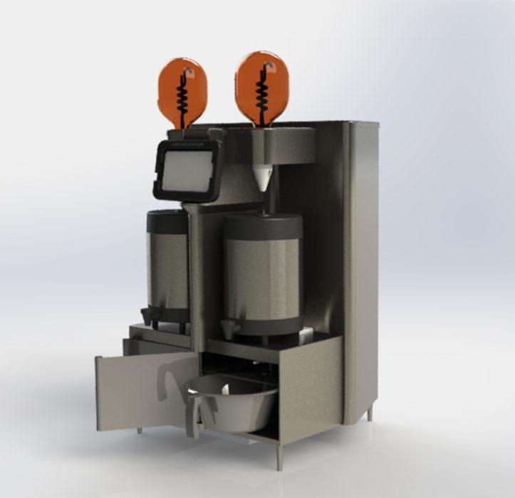
Figure 2
This CAD model of the coffee maker is roughly what the industrial designers asked for. The prototype was an amazing apparatus. It was not quite beautiful, but certainly exotic. With enough welding and grinding, multiseam designs like this can be fabricated in small batches. However, an immediate DFM goal was to reduce cost.
In this case the internal detail and planning emerged simultaneously with the physical assembly of the first prototype. It was not the ideal development plan, but the result satisfied the prevailing constraints of schedule.
While pondering Figure 1b, the ID team tried to anticipate the future in terms of market and end-user acceptance, operational challenges, and peer competition. It should be noted that this brewer goes head to head with several established brands. The competition, however, all use drip brewer technology. This commercial coffee maker has emergent brew technology, which creates an opportunity to differentiate this brewer from its peers. Voga, the company behind the new brewer, focused on gleaming glass as the visual product differentiator.
What is the finest brewer in the world, and how would this be different? The concept of aspirational competition led the ID team to study a variety of machines that are on the market. The coffee maker had to look good when sitting next to a high-end espresso press.
The design review included consideration of the least-expensive brewers available. The market is larger, and the margin is smaller. For this first product line, the decision was made to use high-end materials and finishes.
As the ID team doodled with Figure 1b, they found the rear tower/frame to be too wide. The team’s original intent was for the front of the machine to dominate. That wasn’t too objectionable, but still not their intent.
On the plus side, the glass chambers, while important to the chemistry, were absolutely critical to the ID. The gleaming stainless steel shelf supporting the glass was determined to be a good look.
The ID team had originally intended for there to be no seams around the top of the machine. The emergence of lid seams in the prototype was the result of delegating the method of fabrication with insufficient instruction to the job shop (as discussed in detail in previous episodes).
The ID critics noted that there is an odd combination of large- and small-radius corners in Figure 1b. The front box is really sharp and boxy, just bolted on to the front of a rear tower with style from a different machine. The center partition draws attention to the doors, as if the doors are important.
The doors have handles that are simply formed out of the sheet metal. They are open hems, which are very cost effective, but also a very glaring, cheap contrast to the exotic, expensive glass.
From an operational point of view, the coffee maker needs a service door on the side, not the rear. Functionally, the brew basins and doors are not working well in the prototype. The carafe deck is very hard to keep clean with the center partition between the carafes.
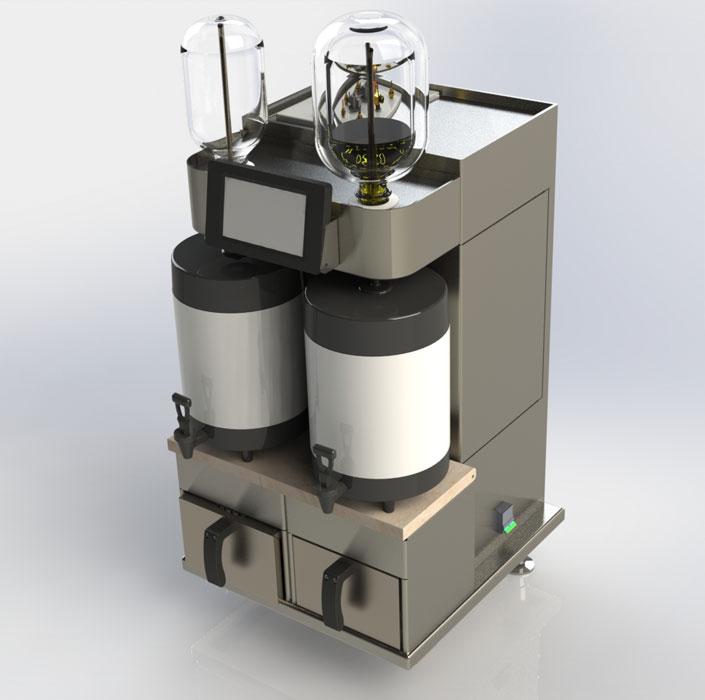
Figure 3
The DFM team responded with the Version 2 CAD model. Brew boxes replaced doors. Side service panel were created. Visible top lid seams were eliminated. The design reviewed with the ID team was mostly approved with some exceptions: get rid of the side power switch and bottom tray.
The DFM team departed the meeting with a useful set of design constraints. The internal models remained key to success with the frame and covers. A second CAD model was prepared for review.
Figure 2 shows the model that was reviewed at the next meeting. A substantial amount of welding and grinding had been removed from the prototype’s design.
The big change was the rear tower. Using the internal plumbing as one constraint and the width of the brew basins as another, the DFM team made the rear tower narrower than the front box, but not by much. This satisfied an ID goal.
Locating the service panel on the cabinet’s right side also was an acceptable design feature, although it was not clear how that cover would latch in place. The side covers extend past the top lids to hide the seams, which helped to obtain the look that the industrial designers were after. Again, this concept model did not include fasteners to hold the lids in place. As a guideline, when no other thing matters, the default fastener size was selected as M5/10-32.
The favorable tooling cost for sharp corners led to making almost all sheet metal corners with minimum bend radius. Using cost and strength as guides, the DFM team made the bottom frame out of a simple rectangle. That left a dust-collecting edge as seen under the power switch in Figure 2.
Figure 3 reveals a few more design features that were modeled quickly during the meeting or later that same day. The control tablet at the top of the machine has a tilt mount. The carafe deck is made from countertop material and is hinged for service. The service doors lift of to reveal the front as well as the sides of the machine.
The meeting ended with a task for DFM: Add detail to this concept model to show how the frame and covers might be built. The goal for the next review is to show the industrial designers what the machine will look like with seams and fasteners.
Gerald would love for you to send him your comments and questions. You are not alone, and the problems you face often are shared by others. Share the grief, and perhaps we will all share in the joy of finding answers. Please send your questions and comments to dand@thefabricator.com.
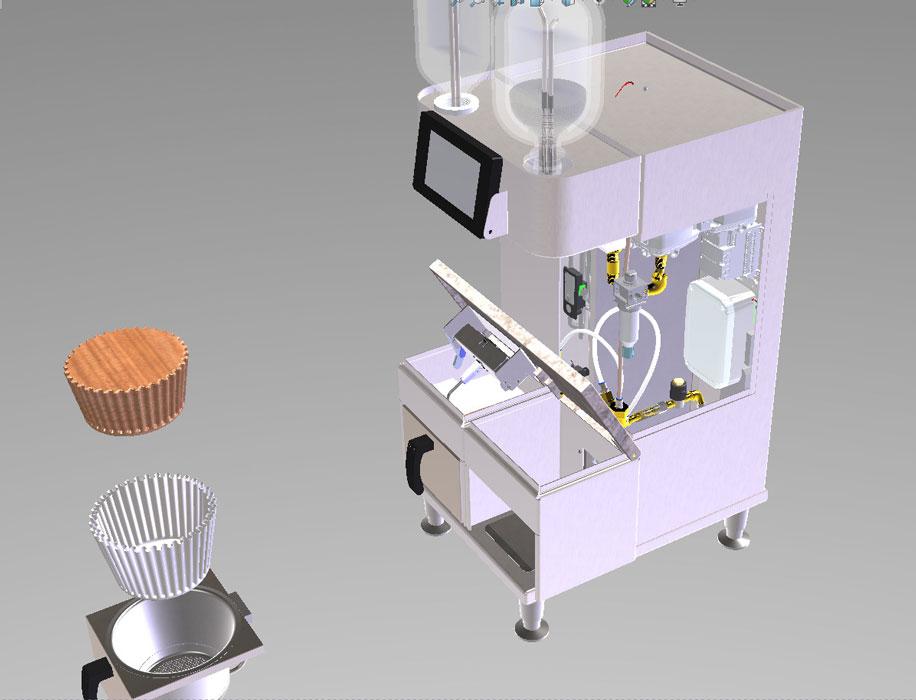
Figure 4
As a refinement to Version 2, the power switch was relocated, and a dust-collecting edge around the floor was removed. The DFM team suggested hinging the carafe deck for service access. Signoff was given to proceed with designing the framework.


The Fabricator is North America's leading magazine for the metal forming and fabricating industry. The magazine delivers the news, technical articles, and case histories that enable fabricators to do their jobs more efficiently. The Fabricator has served the industry since 1970.
start your free subscription
Easily access valuable industry resources now with full access to the digital edition of The Fabricator.

Easily access valuable industry resources now with full access to the digital edition of The Welder.

Easily access valuable industry resources now with full access to the digital edition of The Tube and Pipe Journal.

Easily access valuable industry resources now with full access to the digital edition of The Fabricator en Español.
Patrick Brunken, VP of Addison Machine Engineering, joins The Fabricator Podcast to talk about the tube and pipe...