


Contributing Writer
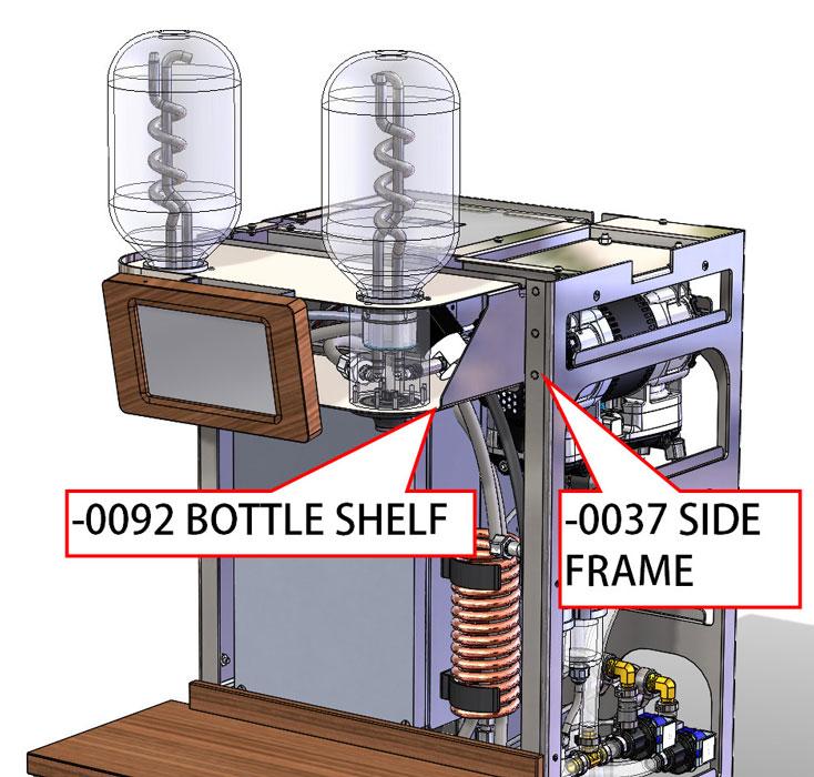
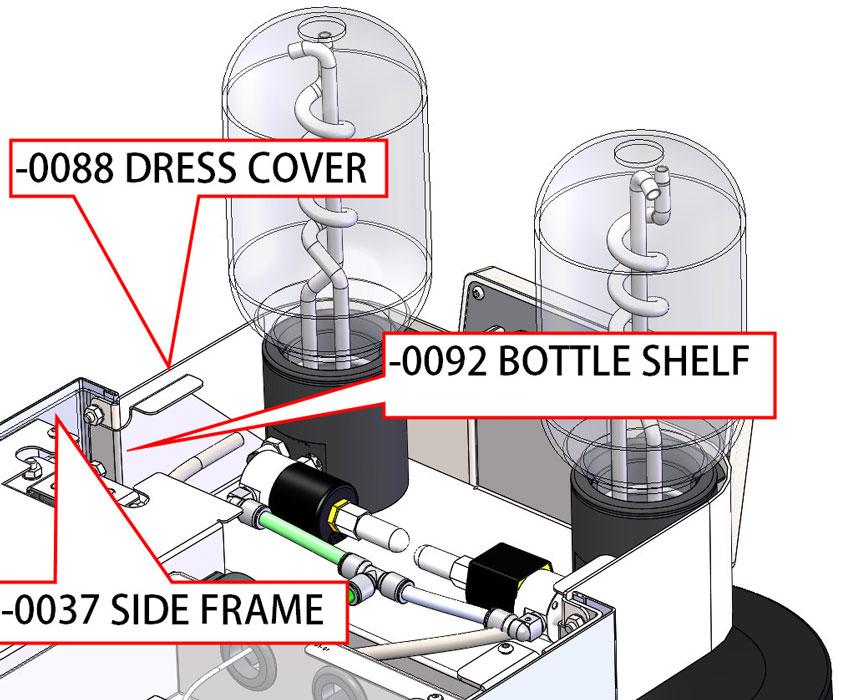
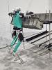
Figure 1
As a method of assembly, studs in the side frame hold the bottle shelf in place.
Disclaimer: This case study of a coffee maker’s sheet metal cabinet features a pair of inventors doing their best at bringing a new product to market. The result was an award-winning product design in 2018. Over several years, they gained experience in our fabrication trade, sometimes painfully. It is very brave of them to share this with us.
Editor’s Note: The author’s explorations in design for manufacturability (DFM) are presented as an example of the kind of effort that goes into a DFM project, particularly one involving an industrial design (ID) team that is committed to a vision.
In the previous edition of this column (“A 3-D CAD modeling case study: When the DFM model reflects an increasing commitment to how over why,” Precision Matters, The FABRICATOR®, October 2018, p. 60), the DFM team added detail regarding interior components and developed a sheet metal frame system shown in Figure 1. The vertical side frame (-0037) is the main structure and provides mounting hooks (jog bends) for external side covers as well as PEM® studs for anchoring the bottle shelf.
From the get-go the industrial designers on this project wanted to hide all bolts. They wanted smooth and sleek as opposed to steam punk in appearance. As a general guide, narrow is better than wide. The front cover of the machine is the one most frequently removed for service. All other covers come off only for major repair.
With these guidelines in mind, the DFM team proposed the cover system shown in Figure 2. The perimeter edges of the top covers are hidden by the extending vertical side covers. The rear cover comes off first, then the front cover slides off around the bottles.
After the front cover is removed, the screws holding the side covers in place are visible. Note that the side covers have rectangular tabs/flanges that hide the bolts visible in Figure 1.
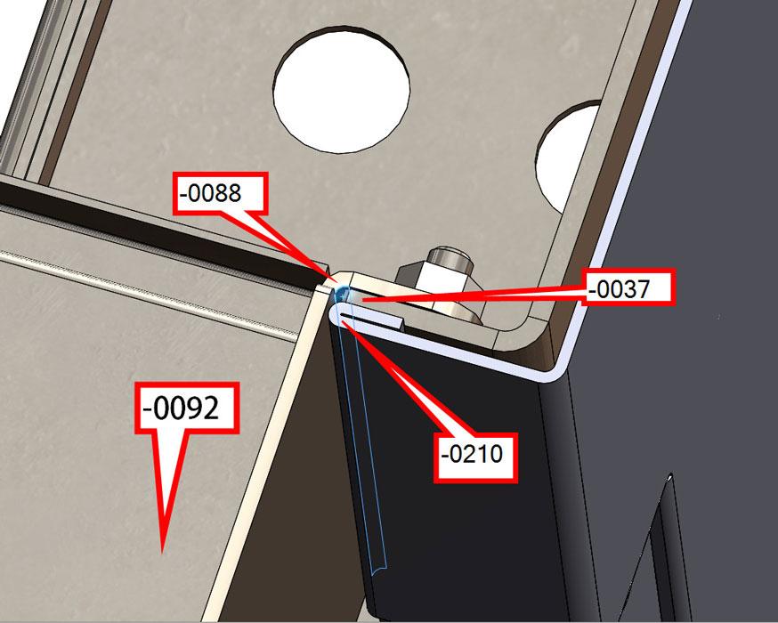
The top covers are removed in Figure 3 to reveal how the frame assembly is bolted together—at least in theory. The dress cover (-0088) is preattached to the side frame (-0037) with a nut on just the top PEM stud (left and right). Then the bottle shelf (-0092) tucks in and slides over the remaining four PEM studs and get nutted into final position.
Here’s a DFM tip: Do all you can to anticipate access for wrenches as well as sequence of assembly. Drag the components in 3-D to discover interference as things come together.
In this example, the DFM team did OK with inventing things to bolt together, but failed to take into account the bulk of the bottle assemblies and nuisance of holding several parts in alignment while trying to install nuts hidden in deep recesses.
With some concerns regarding assembly in mind, please consider the sandwich of sheet metal shown in Figure 4. The removable side cover (-0210) hides the PEM heads in the side frame (-0037). The lovely grained stainless steel side dress cover (-0088) also supports the bottle shelf (-0092).
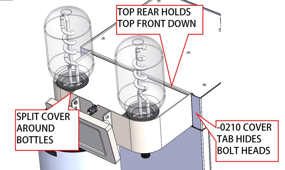
Figure 2
Several industrial design goals are met by this design for manufacturability proposal: Top covers are hidden, no screw heads are visible, front section is narrow. For service, take off rear cover and slide off front top cover
After fabricating and assembling a test unit, our heroes conducted a review. There was good news: The hem on the edge of the removable cover helped reduce paint chipping along edges as it slid on and off. Hems in this application were a success.
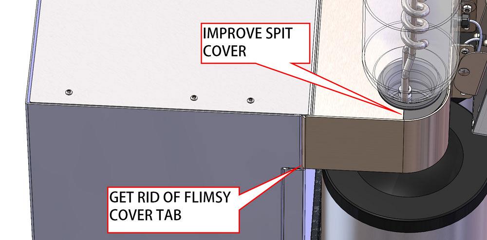
However, there was bad news regarding the side cover: The simple rectangle is fabricated from relatively thin sheet metal. It was very easy to bend. Even though the DFM team succeeded in hiding bolt heads, the fragility of these side covers was such that even cautious service techs could not handle them without damage.
How about some news that falls in between good and bad? The stars of our story, the inventors of this coffee brewer, were wary of new designs and opted to only build just one of the critters shown in Figure 1. That’s how they learned that that side covers were too feeble and that the top covers were very hard to slide together.
Within minutes of hearing about the problems, the DFM team rolled out Figure 5 as a possible design improvement. The side cover without the small rectangular tab was much more robust and much easier to install. Splitting the front top cover resulted in two pieces that were pretty easily installed.
Could this round of prototype and redesign been avoided? Possibly. Building a batch of one is pricey and burns several weeks of time. There is a lot of incentive to get it right before it is fabricated.
How much proofing can or should be done in 3-D CAD before committing to metal? In this example, what felt like reasonable DFM effort was put into simulation, particularly with alignment and wrench access. Most of the attention was on all the things that should have been mounted. The obvious, like a little tab that will bend too easily, was studiously ignored.
Here’s another DFM tip: Follow ID’s example. Use physical samples of material to allow the review team to experience the look, feel, and heft of what is being proposed.
Perhaps flexing a 2- by 4-inch test coupon of 22-gauge stainless would have prompted someone to ask, “Is this strong enough?”
Gerald would love for you to send him your comments and questions. You are not alone, and the problems you face often are shared by others. Share the grief, and perhaps we will all share in the joy of finding answers. Please send your questions and comments to dand@thefabricator.com.


The Fabricator is North America's leading magazine for the metal forming and fabricating industry. The magazine delivers the news, technical articles, and case histories that enable fabricators to do their jobs more efficiently. The Fabricator has served the industry since 1970.
start your free subscription
Easily access valuable industry resources now with full access to the digital edition of The Fabricator.

Easily access valuable industry resources now with full access to the digital edition of The Welder.

Easily access valuable industry resources now with full access to the digital edition of The Tube and Pipe Journal.

Easily access valuable industry resources now with full access to the digital edition of The Fabricator en Español.
Patrick Brunken, VP of Addison Machine Engineering, joins The Fabricator Podcast to talk about the tube and pipe...


