Independent welding consumables professional
Nino Mascalo and Rob Koltz help a manufacturer of carbon steel pressure vessels unearth why he’s having trouble increasing submerged arc welding (SAW) throughput.
You have many variables to consider when optimizing welding production, such as weld joint geometry, joint prep, weld joint fit-up, wire diameter, deposition rates of weld parameters, and submerged arc welding (SAW) processes that minimize weld defects. All of these factors work together to determine the quality of your weld.
In Part I we discussed how to maintain material integrity throughout the welding process. With heat input control as our same focus point, we discuss how to maximize welding parameters, but first we’ll address other key areas.
Since SAW is typically an automated process, we'll optimize the applications around it. SAW provides you with several options to achieve your production goals. Your application is a single-wire, which is most prevalent in industry, but twin-wire, tandem-wire, and tandem-twin-wire configurations are used throughout the industry too. The option chosen will largely depend on your equipment capabilities.
If you have only a single 1,000-amp direct-current (DC) power source, you will most likely run large-diameter single wire or possibly 3/32-in.-dia. twin wire. If you have multiple power sources, you may be able to take advantage of one of the other wire configurations for increased deposition.
The first place to start with process optimization is the quality and consistency of your joint bevel and fit-up, which is often overlooked. A cost-effective, efficient way to produce quality weld joints is to utilize a burn table with a multiaxis plasma head or oxyfuel setup that can produce various joint geometries. This should produce repeatable, consistent beveling of the plates, assuming the equipment is maintained properly and in good working order.
The beveling capacity available will help determine which weld joint option to select. Some manufacturers prefer a single V-groove and others an offset double V-groove, although there are others as well. Since pressure vessels are complete joint penetration (CJP) weld joints, and in many cases access to the back side of the weld joint is either limited or not possible, choosing an open-root V-groove joint is most logical, which is the case with your application.
You stated you weld a 1/8-in. open-root joint using gas metal arc welding (GMAW). This is a fairly common practice throughout the pressure vessel industry and there is no need to change it. With that being said, the need to put one SMAW hot pass on the inside is not necessary if your technique and weld parameters are sufficient to deliver complete penetration.
The purpose of open-root welds is good weld joint fusion on both sides without excessive weld reinforcement on the opposite side of the joint that was welded. The opposite side welded should have smooth weld toe transitions and be free of undercut.
This weld could be produced using short-circuiting transfer (SCT) mode, ideally with a 0.035- or 0.045-in.-dia. ERXXS-2, S-3, or S-6 solid wire with the appropriate shielding gas. The S-6 wire has more silicon, which helps with weld puddle fluidity and produces smooth weld toe transitions, but it also can be difficult to prevent the weld from appearing too ropey or convex. In those cases, an S-2 wire may perform better.
The weld bead thickness is an important point with the GMAW root that is often overlooked. If the welds are made in various positions around the weld joint, such as near the top or down the side, the thickness may vary due to gravity pulling on the weld puddle and thinning it out as it solidifies. This may potentially cause areas of burn-through in your first SAW pass.
You mentioned you run two hot passes with E7018 SMAW. Welding two hot passes before SAW to prevent the subarc from burning through can be very time-consuming. Flux-cored arc welding (FCAW) can be a more welder-friendly process and save considerable time. With a large-diameter flux-core wire, your travel speeds could be as high as 15 to 18 inches per minute (IPM). You will also benefit from high deposition efficiencies and rates compared to SMAW, and FCAW may be able to do it in only one pass.
Now we need to consider which weld parameters to optimize.
You didn't mention what polarity you are using, but we will assume constant current, direct current positive, otherwise known as reverse polarity (CC-DC+). This polarity provides a stable arc and good penetration, which is important for side-wall fusion at higher welding currents. This polarity is used predominantly in industry.
Additionally, the vessel’s diameter will also play a role in optimizing weld parameters. Large vessels are easier to weld, but small-diameter vessels (less than 30 in.) have some limitations. This is because of the solidification rate of the molten weld puddle and where that occurs with respect to top dead center (TDC) of the vessel’s weld joint. Gravity pulling on the weld puddle will dictate maximum welding current and travel speed. Positioning the SAW head with respect to TDC will be determined by bead appearance and weld parameters. The goal is to get the weld to solidify near TDC as the vessel rotates, so the SAW head should be located approximately 1 to 4 in. in front of this location to keep the molten weld pool from rolling in front of the welding arc.
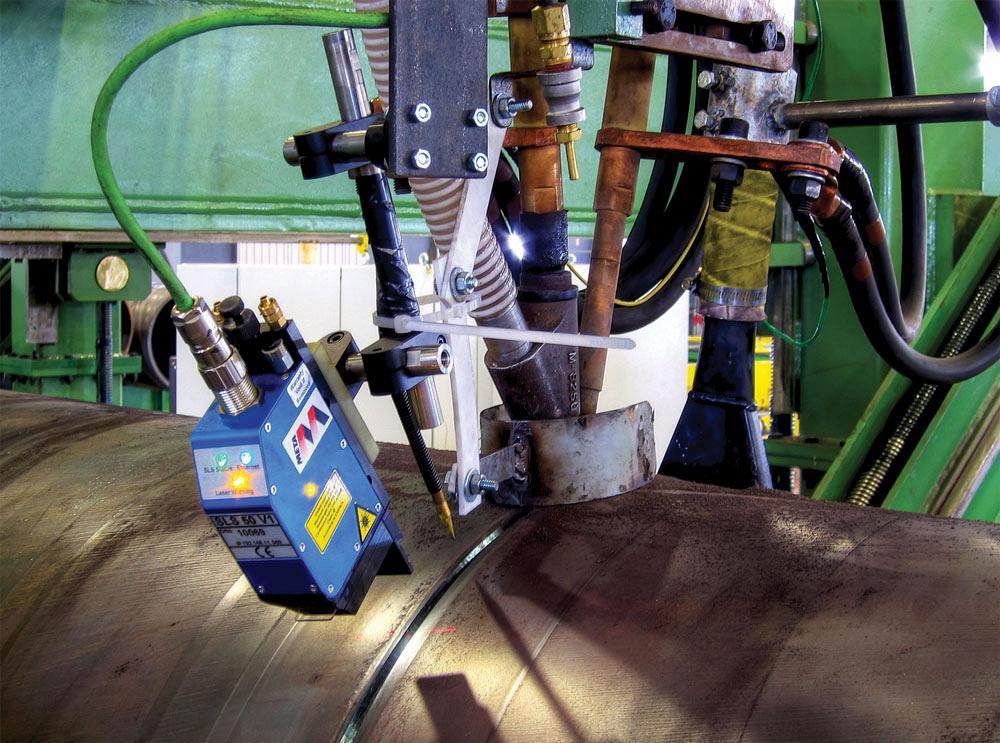
If your system does not have automatic joint tracking, the process will be limited to how good the operator is and how fast they can make adjustments to accommodate joint variations as the vessel “walks” or changes in electrical stickout (ESO) due to variations in vessel roundness. In most cases, this situation might limit you to 18 IPM. At these slower travel speeds, weld productivity is limited by the weld’s heat input.
Ideally you should have auto-height tracking to maintain consistent ESO, along with a laser light that allows you to track the joint properly from side to side. Also, using a camera system lets you track welds remotely. With similar configurations, you should be able to achieve weld travel speeds as high as 25 to 35 IPM with a single-wire application.
You can run the first SAW pass at slightly lower travel speeds, depending on all previous conditions. The key with the first one or two passes is to have a bead shape promoting a free-peeling slag. If the slag locks in the joint, the parameters were likely incorrect.
Excessive voltage creates a wider weld bead with a flatter, or in this case concave, bead. To have the slag-free peel, you want to have a slightly convex bead, and to get that you may need to decrease your voltage by 1 or 2 volts. Alternatively, or in addition to the voltage adjustment, increase the weld travel speed to effectively deposit less weld. When you go faster, the weld metal does not have time to spread out and lock in the bevel.
The first SAW pass produces the weld bead most prone to weld defects. For this reason, select the weld parameters to ensure there are no burn-through issues and achieve excellent bead shape without compromising productivity. Weld defects may arise from incorrect welding parameters that result in too much metal in a too small area of the bevel. The specific problem is the weld puddle runs in front of the weld arc.
Once you're beyond the narrowest part of the joint, you can focus on weld deposition by increasing amperage and selecting a voltage and travel speed to deliver the desired bead size and shape necessary to produce a quality subsequent weld bead. This is why a weld procedure specification (WPS), based on a procedure qualification record (PQR), is written. The goal is to maximize current/weld deposition to deposit the most weld metal in the fewest passes.
Your PQR established the maximum weld heat input at about 75 kJ/in. As mentioned earlier, single-wire applications typically top out at travel speeds of 35 IPM. However, a good starting point is 25 to 30 IPM. With that information, using the heat-input equation, and knowing the high end of the voltage will be somewhere between 30 and 32 V for the fill portion and 32 to 35 V for the cap, this leaves us with high-end welding currents ideally between 800 and 1,000 amps. If we take the highest expected voltage and amperage of 32 V and 1,000 amps, we calculate a travel speed of 25.6 IPM minimum is required to meet a maximum heat input value of 75 kJ/in.
This preliminary calculation gives you a starting point to make the weld. Following this convention, you will be able to stay close to the targeted maximum heat input that produces the highest possible weld deposition and the fewest number of weld passes while still maintaining the required mechanical properties.
Once you know the optimal welding fill parameters and the weld’s bead shape, avoid making unnecessary changes. Historically, the fewer changes required, the easier it is for you to track the joint. This results in sound, quality welds and simplifies the process. In most situations, keeping travel speed constant and adjusting volts or amperage to get the desired results is the best approach.
Finally, the last layer of weld, known as the cap, is made to promote a surface that will meet the code requirements in the as-welded condition. As excessive reinforcement results in nonproductive grinding, you will typically reduce amperage (weld metal) and increase voltage to produce weld beads that have minimal reinforcement or excessive weld metal that rises above the surface of the base material. To achieve this, reduce the amperage approximately 15 to 50%, and cut the travel speeds 15 to 30% to allow the weld metal to spread.
Overall this discussion is a generalized approach to optimizing SAW for pressure vessels. Other variations of joints or wire setups we didn't discuss could work just as well. Just as a sprinter does not start running marathons without training, you should work these adjustments into production over a period of time, with development work done on test plates to develop weld parameters.

Independent welding consumables professional


The Welder, formerly known as Practical Welding Today, is a showcase of the real people who make the products we use and work with every day. This magazine has served the welding community in North America well for more than 20 years.
start your free subscription
Easily access valuable industry resources now with full access to the digital edition of The Fabricator.

Easily access valuable industry resources now with full access to the digital edition of The Welder.

Easily access valuable industry resources now with full access to the digital edition of The Tube and Pipe Journal.

Easily access valuable industry resources now with full access to the digital edition of The Fabricator en Español.
In this episode of The Fabricator Podcast, Caleb Chamberlain, co-founder and CEO of OSH Cut, discusses his company’s...