Independent welding consumables professional
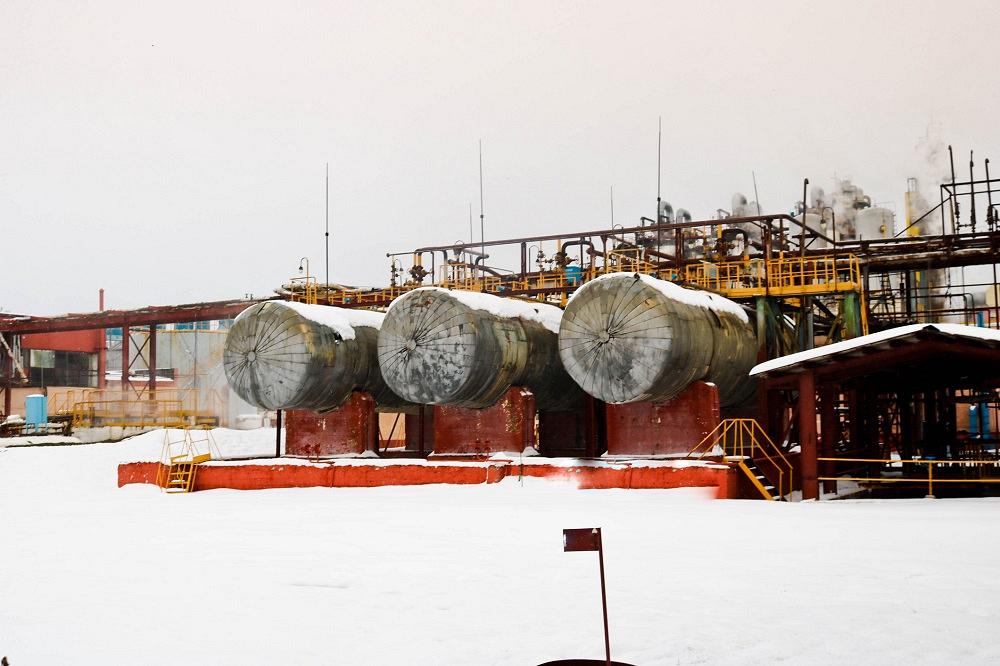
Nino and Rob help a manufacturer of carbon steel pressure vessels unearth why he’s having trouble increasing throughput. Getty Images
Q: We manufacture carbon steel pressure vessels and we're having trouble increasing our throughput. We currently weld a 1/8-in. open-root joint with gas metal arc welding (GMAW). On the inside we back-weld one pass of E7018, grind the outside to clean up the joint, run two 5/32-in.-dia. E7018 hot passes, and then full weld with 5/32-in.-dia. submerged arc welding (SAW). We're running about 32 V and 500 amps at 14 inches per minute (IPM), and the vessels range from 1 to 3 in. thick.
A: When it comes to optimizing a welding process for any application, you should always consider the material type and condition, the preheat/interpass temperatures, welding process, filler metal wire and flux, part fit-up, and the skill level of your welders, just to name a few.
With any weld manufacturing application, the first thing to consider is what steps are necessary to maintain the integrity of the design and base material’s mechanical properties. This includes the material’s yield and tensile strength, impact toughness, and elongation.
An important variable that will influence the impact toughness is a weld’s heat input. Other variables such as preheat and interpass temperature, along with postweld cooling rates, can play significant roles as well. However, if your heat input is too high, the impact toughness will be degraded.
For ASME applications, the impact properties are measured by Charpy V-notch (CVN) testing. A procedure qualification record (PQR) is welded with CVN testing as part of the required mechanical testing and a maximum heat input established. In a situation where you are using a GMAW root pass, SMAW hot pass, and SAW fill passes, all three processes will have an established maximum heat input.
For the root-pass weld, a potential issue you may encounter is welding energy that is insufficient to establish good fusion with the base materials. In similar applications, manufacturers use a 0.035-in.-dia. solid wire with 75 percent argon/25 percent carbon dioxide shielding gas mix in short-circuiting transfer (SCT) mode. If the weld parameters are not robust enough or the welder lacks the necessary training and skills, he risks a lack of fusion (LOF) that can sometimes be hard to detect. Maintaining a minimum heat input above 20 kilojoules per inch (kJ/in.) should help minimize the risk of LOF.
With the SMAW hot passes, unless you are using an amperage or travel speed that is outside the manufacturer's recommendations, there should not be any issues with heat input, provided you are welding stringer beads. Typically, if you are depositing weld beads that are approximately 3/8 in. wide with a 5/32-in.-dia. electrode, the heat input and quality of weld should be satisfactory.
For the SAW fill passes with the parameters you provided, the heat input calculated is 68.6 kJ/in. This value falls in a range we consider to be optimal for welds that produce good filler metal and heat-affected zone (HAZ) base material mechanical properties.
In weld manufacturing, the “safe” range for heat input falls between 25 and 75 kJ/in. However, in some cases less than 25 kJ/in. is ideal and in many cases more than 75 kJ/in. is ideal for the application.
If you are dealing with a steel grade that is sensitive to high heat input, for example a quench-and-tempered (Q&T) material, or an application that requires good cold weather toughness, such as impact values at -40 degrees F or below, then the upper limit on heat input becomes lower.
The main concerns with excessive heat input are the effects on the HAZ of the base material or weld metal. With many steel grades, especially the Q&T, if you exceed a certain heat input value, the material’s toughness decreases. Usually this happens by way of a significant microstructure change via grain growth. Another concern is the formation of martensite, which we discussed in a previous column.
Sometimes you can alleviate this by using the proper preheat and controlling postweld slow-cooling rates. In many other cases, simply keeping the heat input below the recommended upper limits will help minimize the problems.
A unique feature about welding is that, in most instances, the process itself, along with some basic physics principles, prevents misuse. For example, if you’re welding out of position (horizontal, vertical-up, or overhead), gravity will mostly prevent you from depositing an excessively large weld bead. Welding in the flat position, especially in groove weld joints, allows the welding process to deposit very large weld beads, either by slowing the travel speed down or using excessive weld deposition rates in order to fill up the joint.
This is particularly true with weld joints that require multiple passes to fill. You may think you are saving time by depositing large beads and thereby reducing the number of weld passes required to fill the joint, but the integrity of the weld metal and base material may be compromised.
With SAW you have the ability to increase the welding parameters and still produce a weld that has a satisfactory appearance. But if the heat input is not controlled properly, the weld may in fact have poor mechanical properties. In your situation, if we take a 5/32-in.-dia. SAW wire, weld at 14 IPM, and increase to 34 V and 900 amps, the heat input is now calculated at 131.1 kJ/in. At this high value, we expect to see a significant decrease in toughness. This is why PQRs are welded to establish the maximum welding parameters to deliver the required mechanical properties.
As we mentioned earlier, it is important to follow recommended preheating guidelines, to stay under the recommended maximum interpass temperature and heat input, and finally to control the cooling rate of the weld.
We will discuss how to optimize the process for improved throughput in Part II.

Independent welding consumables professional


The Welder, formerly known as Practical Welding Today, is a showcase of the real people who make the products we use and work with every day. This magazine has served the welding community in North America well for more than 20 years.
start your free subscription
Easily access valuable industry resources now with full access to the digital edition of The Fabricator.

Easily access valuable industry resources now with full access to the digital edition of The Welder.

Easily access valuable industry resources now with full access to the digital edition of The Tube and Pipe Journal.

Easily access valuable industry resources now with full access to the digital edition of The Fabricator en Español.
In this episode of The Fabricator Podcast, Caleb Chamberlain, co-founder and CEO of OSH Cut, discusses his company’s...