


Contributing Writer
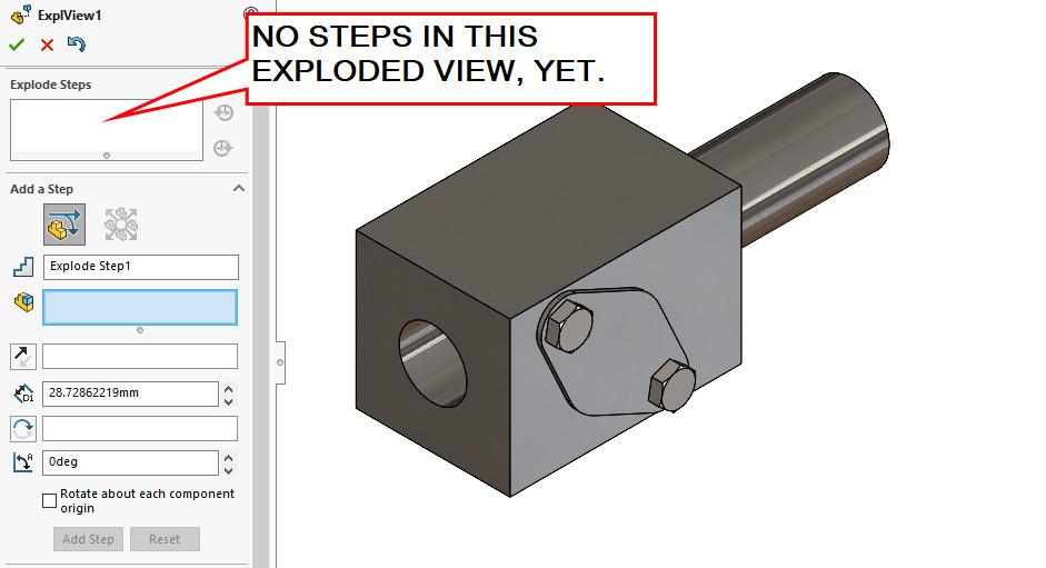
FIGURE 1. Exploded Views reside in an assembly and consist of Explode Steps. When a new Exploded View is created, it has no steps. No components have been repositioned.
Exploded Views are useful for illustrating how components are related. To demonstrate the process of adding an Exploded View to an assembly and then adding Explode Steps to it, the assembly in Figure 1 will be used.
Figure 1 shows our assembly after a new Exploded View is first added. An Explode Step is ready to be added.
Figure 2 shows the setup for the first Explode Step. Here’s a CAD tip: Select various related items so they reposition as a group. In later steps, separate the parts in that group. This can be handy later when refining the Exploded Steps, as we shall see.
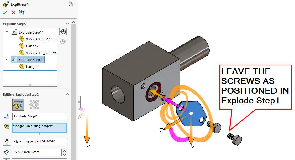
In Figure 2, a cover and two screws have been repositioned as a group. Figure 3 shows the cover after it has been repositioned away from the group. Good progress is being made. The next step is to move the just-exposed O-ring.
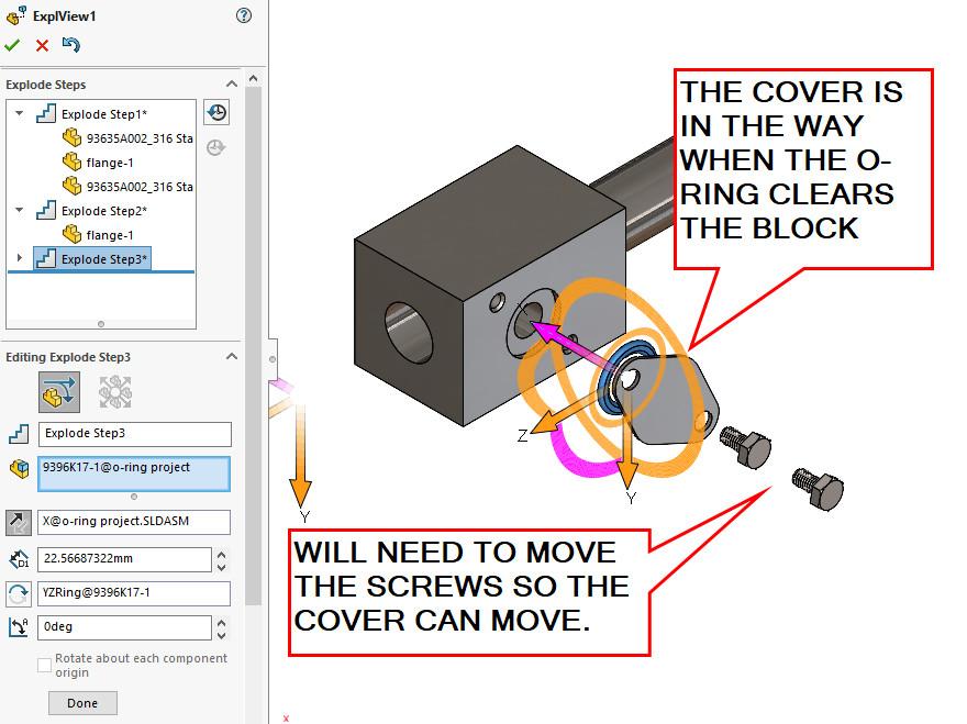
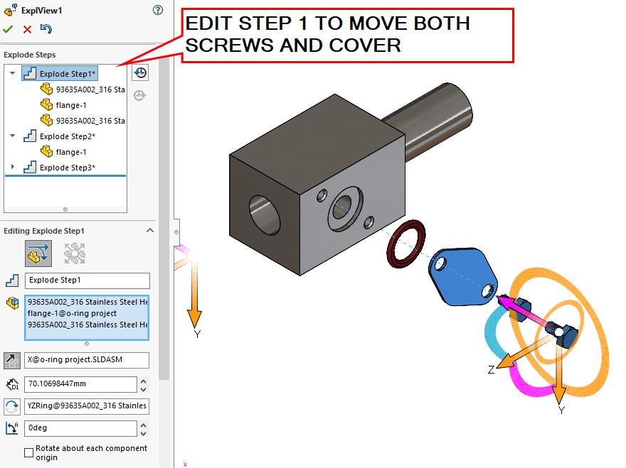
In Figure 4A, the O-ring is easily positioned away from the machined block. Sadly, the cover obscures the O-ring’s best position. The cover must move, and the screws are in the way of the cover.
In Figure 4B, the first Explode Step is edited to reposition the entire group to properly reveal the O-ring. This is the end of the CAD tip regarding grouped Explode Steps. For this demonstration, five Explode Steps will almost complete the creation of an Exploded View.
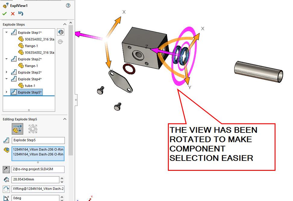
Sometimes it is easier to select components for repositioning after rotating the view. In Figure 5, the model has been rotated for convenient selection and repositioning of a couple of O-rings.
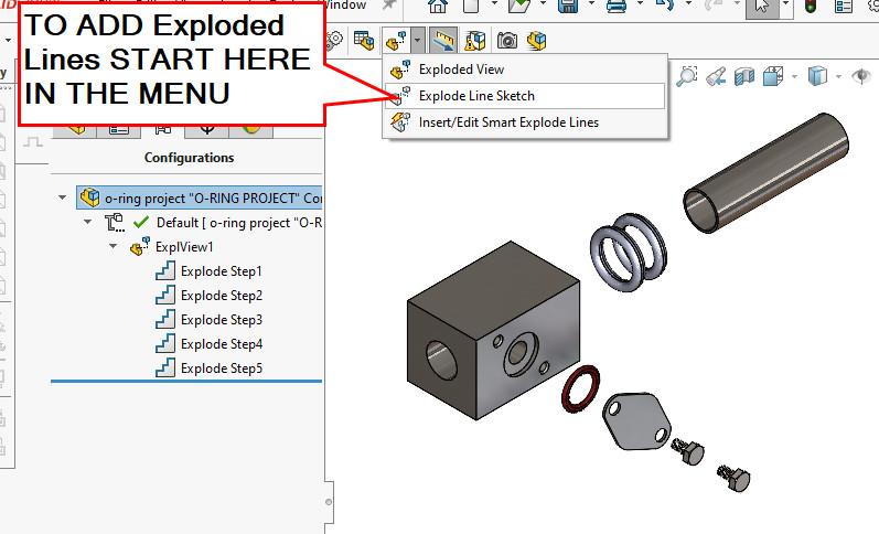
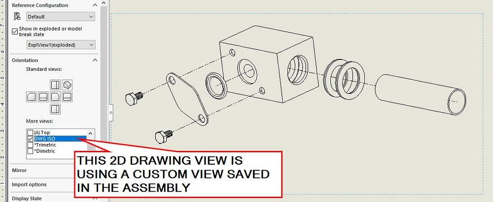
To complete the Exploded View, after the components are in the desired position, the addition of an Exploded Line Sketch helps the audience make the connection. Figure 6A shows the drop-down menu selection for an Exploded Line Sketch. Use this tool to create a 3D sketch of lines that connect the exploded components.
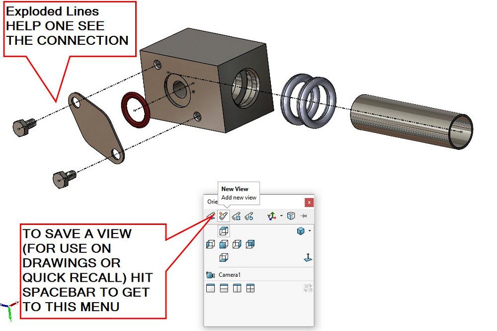
Figure 6B shows the result of adding an Exploded Line Sketch. Use the tool to select components (and the direction of the lines). Please also note the custom point of view in Figure 6B. The model is currently viewed so that the components are all visible. The standard isometric projection of this model doesn’t do that.
As we conclude this tour of Exploded View creation, we note that:
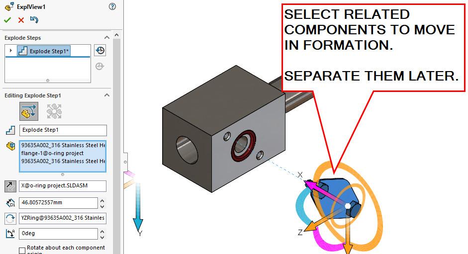
FIGURE 2. As a CAD technique, create Explode Steps with groups of related parts. This will be useful later when refining the repositioning.
O-ring glands and Exploded Views don’t have much in common. However, the specification of grooves and pockets for O-rings is a useful design skill. Here’s a career tip: When collaborating on a team, contributing clear illustrations and well-specified seals are among the skills that will make you welcome.
I’m not affiliated with Apple Rubber, but I am a fan of its online gland calculator tool (www.applerubber.com/oring-gland-calculator). Similarly, I’m not affiliated with McMaster-Carr, but its website is useful for O-ring cross-sectional measurements (its DASH size) and offers downloads and (at least preliminary) answers for where to find things.
In general, an O ring is used for creating a face seal against its cover. The O-ring is sealing against internal pressure.
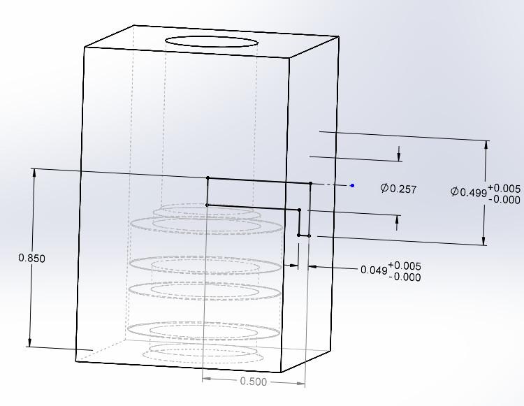
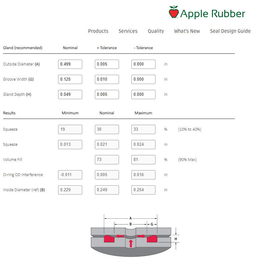
Figure 7A features a sketch for a Cut-Revolve for that O-ring’s gland. The dimensions and tolerances used were discovered online using Apple Rubber’s gland calculator (see Figure 7B). Tell the calculator that it is a face seal for a DASH-012 size O-ring against internal pressure. The calculator returns a starting suite of dimensions that can be tuned to optimize the squeeze.
Here’s another CAD tip: Make the dimension scheme in the sketch match the dimensions on the calculator. You can even rename the dimensions to match the ABCs. The people reviewing and editing the gland will appreciate the clarity.
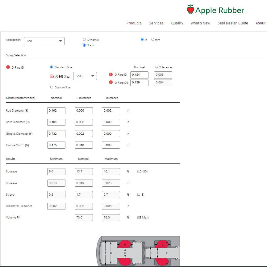
For the O-rings that are sealing against the rod, change the calculator’s application from axial to radial, and update the DASH size desired. (In Figure 7C, it is DASH-206). Disclaimer: There is more to gland design than this starting point calculator.
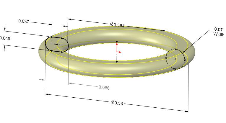
As mentioned, downloads for O-rings are easy to find. However, it doesn’t take much to model an O-ring from scratch—a dashed line and a slot or circle. In Figure 8A a Revolved Sketch shows the deflected O-ring for the rod seal. The dimensions for deflection are borrowed from the gland calculator. Similarly, in Figure 8B, the face seal O-ring is modeled to show its squeezed flatness.
Figure 9 is the encore shot showing the deflected O-rings doing their duty. Deflection is a small thing to show but is sometimes a way to spot an error.

The Fabricator is North America's leading magazine for the metal forming and fabricating industry. The magazine delivers the news, technical articles, and case histories that enable fabricators to do their jobs more efficiently. The Fabricator has served the industry since 1970.
start your free subscription


Easily access valuable industry resources now with full access to the digital edition of The Fabricator.

Easily access valuable industry resources now with full access to the digital edition of The Welder.

Easily access valuable industry resources now with full access to the digital edition of The Tube and Pipe Journal.

Easily access valuable industry resources now with full access to the digital edition of The Fabricator en Español.
In this episode of The Fabricator Podcast, Caleb Chamberlain, co-founder and CEO of OSH Cut, discusses his company’s...


