


Contributing editor
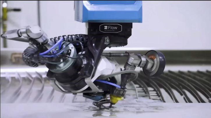
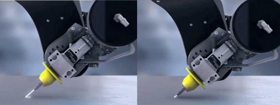
Here is a 3D head with taper compensation cutting a part at a severe angle with Flow’s Compass™.
Waterjet technology has managed to resolve challenges related to stream lag and taper in 2D cutting through the years with progressively improving technology. To resolve the taper and stream lag encountered in two-dimensional waterjet cutting, technology advancements have compensated for these inherent errors without needing to significantly reduce cut speed.
As waterjet cutting moves into the third dimension, think about the complexities that 3D cutting adds. What makes cutting 3D parts even more challenging? Now, there are varying degrees of angles on one part, as well as thickness variations in the material. As the cutting head tilts through a piece of material, the cut becomes deeper because the material is thicker at an angle. Additionally, head rotation and a change of feed rate are required to cut at angles instead of just vertically.
3D cutting involves many more variables that all need to be accounted for—not only for an angled cut but an accurately angled 3D cut. A fourth, dynamic jet head allows fabricators to get the precision they need in 3D cutting.
3D waterjet cutting is not new. Five-axis, 3D waterjet cutting has been performed to produce parts for aerospace structures for more than 30 years. It is also used in the automotive industry.
There was one major challenge to making 3D cutting mainstream, and that was the cost of those systems. Highly engineered, custom systems are very expensive—and not easy to program. But as technology advances, 3D waterjet cutting systems have become easier to use at a more affordable cost.
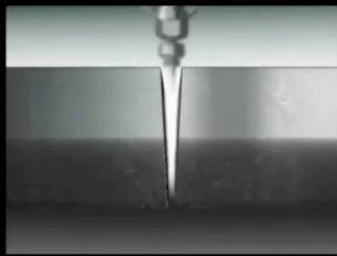
Most shops are familiar with the simplest form of 3D cutting—beveling. What’s the difference between bevel cutting and 3D cutting using solid modeling?
In bevel cutting, the entire edge has a constant thickness. The wrist is set and holds position. The stream behaves like 2D cutting, but at an angle. These machines produce simple beveled edges, such as for weld prep. In fact, weld prep is a very common application for bevel cutting.
In addition, an entry-level waterjet cutting machine can be used for pre-machining removal of material. Sometimes it makes sense to rough-cut to remove as much as you can and then perform secondary finishing it on a machining center. It can save a lot of time to quickly near-net cut rather than use a precision machining operation for all of the material removal.
Generally, this type of machine is suitable for fabricators that want cost-effective, 5-axis cutting but don’t need high accuracy and don’t want to break the bank.
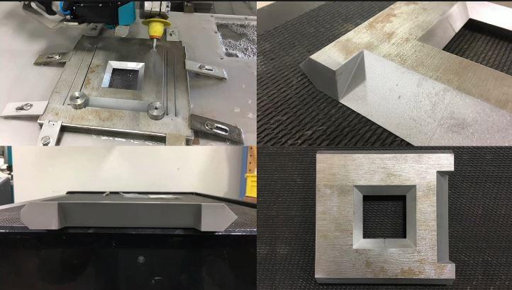
This is a good example of what an advanced cutting head will do when many applications come into play. At the top left, the head is tilted at a severe angle. Very low-profile clamps are holding the piece in place, and the head is cutting at multiple angles around the side of this part. On the bottom left is a K bevel. And then to the right of it is a very sharp, almost knife-blade edge in the middle of the geometry. At the top right is an intricate cutout that requires a lot of articulation in the wrist. And then on the bottom right is an overhead view.
Historically, entry-level beveling and contouring capability has been available only on advanced machines. Now it’s more readily available, affordable, and easier to use for even the most basic beveling capabilities.
What to look for in an entry-level, beveling-capable, 3D waterjet cutting machine:
• Small compact envelope• 5-axis cutting with taper control• +/- 60 degrees of angle cutting capability. If vertical is zero, you want to be able to go 60 degrees.• Low-profile mounting. This is important for fixturing and clamps, so you’re not bumping into things with a 5-axis wrist. • Simplified design for abrasive feed and cable routing to accommodate a wrist that rotates and moves in five axis. It’s different than just having a vertically mounted cutting head on the machine. • Basic contour following, which becomes more critical as you cut things at an angle because the standoff distance changes when you cut things at an angle.
3D head with taper compensation is the next level 3D waterjet cutting. With this technology, you get into true 3D-with-taper-control compensation, which makes up for the natural stream lag inherent with waterjet cutting.
A multi-axis cutting head has 60 degrees of motion, with taper control, and there is a much more advanced, accurate, rigid system in the cutting head itself. The head automatically compensates via software to eliminate taper in the 3D motion as it’s cutting. Plus, it takes into account the speed at which it’s moving in a linear direction, the material thickness, the geometry of the part, and the angle.
Historically, the math behind 3D waterjet cutting was complicated, which goes back to why the technology was only for those advanced aerospace applications over a decade ago. Now, with the help of upgraded software technology, you can predict stream behavior in a multiaxis environment. This advanced software allows high-precision 3D cutting to be more commonly used.
For a programmer to have the knowledge, experience, and waterjet expertise to program all of those variables through G code isn’t realistic—especially if the operation involves multiple cutting applications and a variety of materials and thicknesses. Now, all of that is built into user software modeling.
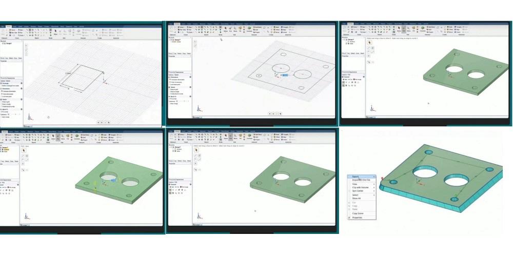
Obviously, it’s not possible to impart an angle to a flat stock piece of geometry. You cannot just take an DXF image and put an angle to it. You need 3D modeling to be able to determine the angles in true 3D form, and you have to know the material thickness to do that. You need to see the part in 3D to add dimension, put a weld prep edge on it, or add 45-degree edge. The software puts a tool path on the drawing. It’s basically a simple, automated function.
An entry-level 3D waterjet cutting machine is fine for cutting bevels.
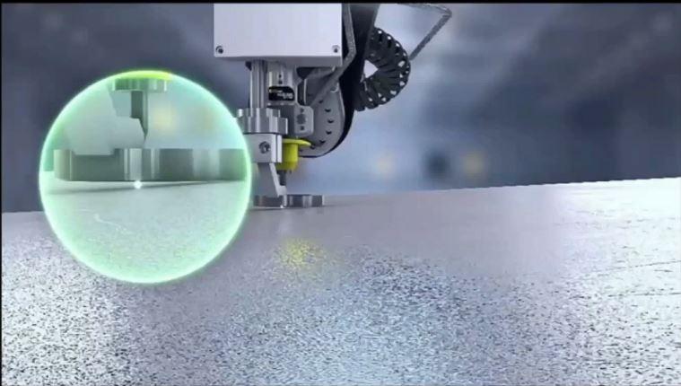
The distance from the cutting head to the material becomes very important when cutting at an angle. 3D cutting a part on a waterjet when the cutting head is angled requires maintaining a constant standoff distance between the nozzle tip and workpiece. If the distance changes, cut accuracy will suffer. If the height varies when the head is angled, the point of contact will move, causing part errors. The waterjet stream will not enter where you want it to enter, causing part errors. Special software is designed to take care of that standoff distance issue.
What happens when your work surface isn’t flat? Now you have a problem because the head is not perpendicular to the material you’re cutting, and an optimal standoff height is not maintained. The more the head is angled, the more pronounced the cutting errors will be. Contour followers exist to solve that problem.
Traditional contour followers measure the standoff height from the outer edge of their contact ring, not from the jet tool center point. The way to resolve that problem is a software-directed cutting head that rotates along the surface of the material to compensate for the height variations of the work material during cutting. The software uses the jet tool center point to measure the standoff height to solve errors when cutting angled, beveled, or stress-relieved parts on non-level work material.
Whether you’re waterjet cutting a finished part or a near-net part, 3D capability is a big advantage. Applications includes aerospace, architecture, electronics, transportation, energy, manufacturing, and automotive.
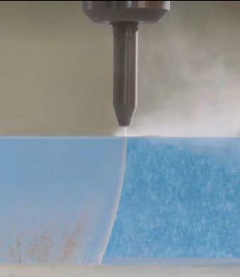
The aerospace segment uses 3D waterjet extensively because it can cut any material of any thickness, including complex and exotic materials, like armor plating and bulletproof glass. The high-precision results and satin-smooth edge quality of a waterjet-cut edge make it suitable for parts such as landing gear, brake components, aircraft bodies, and engine components. Because it is non-thermal, it won’t alter the molecular structure or shape of the material being cut.
3D waterjet is also used in many other applications. It’s used in automotive for trimming door panels and bumpers with robotic systems. In architectural and construction applications, it is utilized to cut stone countertops, tile, glass, and other brittle materials. Electronics are also being waterjet cut because of waterjet’s minimal kerf width and heat affected zone-free cutting, for components that cannot handle the heat stress of other cutting methods.
These and other applications have been made possible through software with 3D modeling. Five-axis waterjet cutting was once very complicated, but now with the software, it’s as simple as it looks.
Content has been adapted from a FABTECH 2021 presentation by Brian Sherick, vice president of global sales for Flow Waterjet, 23500 S. 64th Ave. Kent, WA 98032, bsherick@flowcorp.com, 253-246-3500,

The Fabricator is North America's leading magazine for the metal forming and fabricating industry. The magazine delivers the news, technical articles, and case histories that enable fabricators to do their jobs more efficiently. The Fabricator has served the industry since 1970.
start your free subscription
Easily access valuable industry resources now with full access to the digital edition of The Fabricator.

Easily access valuable industry resources now with full access to the digital edition of The Welder.

Easily access valuable industry resources now with full access to the digital edition of The Tube and Pipe Journal.

Easily access valuable industry resources now with full access to the digital edition of The Fabricator en Español.
In this episode of The Fabricator Podcast, Caleb Chamberlain, co-founder and CEO of OSH Cut, discusses his company’s...


