


Contributing Writer
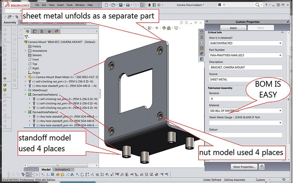
Figure 1a
This camera bracket is modeled with the intent of manufacturing. It mimics an actual assembly of sheet metal and machined hardware. The CAD assembly adds detail and is useful for custom products.
Editor's Note: If you would like to download the 3-D CAD files associated with this column, click here.
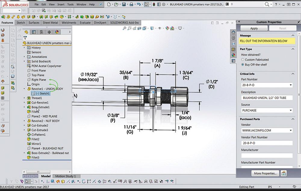
The bracket model captured in a screen shot in Figure 1a includes detail that supports both purchasing and fabrication. With modeling for manufacturing as the design intent, the sheet metal is a stand-alone model. That is to say, it unfolds into an accurate flat layout. The sheet metal part is inserted into an assembly file. Each machined fastener exists in its own file and is likewise inserted into the assembly. This CAD modeling technique is very similar to real-world manufacturing.
In addition to mimicking the actual fabrication process, the assembly modeling technique speeds the production of control documents in which a bill of materials (BOM) is involved. An example is shown in Figure 1b. Speedy creation of the BOM table shown in Figure 1b relied on a library of components that have product manufacturing information (PMI) embedded in them. PMI includes the description and part number for the component. That PMI automatically populates the BOM as it is dropped into the drawing.
Note that four CAD files are required for the assembly—one for each of the machined components, one for the sheet metal part, and one for the assembly.
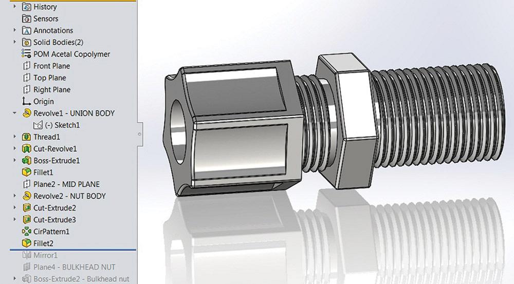
An alternative approach is shown in Figure 1c. Instead of an assembly, a multibody part contains all of the features. A single file holds the sheet metal part as well as the machined parts. Perhaps a benefit of this technique is speed. Inserting and mating a component might take longer than sketching and extruding bodies.
Here’s a CAD tip: The Hole Wizard automatically creates a sketch pattern that can be used to pattern bodies in a multibody model much like patterning components in an assembly.
In Figure 1c the Sketch-Pattern3 of four bodies is based on the Hole Wizard’s Sketch7 pattern. To achieve the same result using components instead of bodies, a CAD jockey should take note of the DerivedHolePattern2 of standoff models, seen in Figure 1a. DerivedHolePattern2 is based on the Hole Wizard pattern embedded in the sheet metal component.
In a comparison of the results of assembly and multibody modeling, the advantage goes to multibody in file count and perhaps in initial modeling time. The assembly modeling technique, however, has profound advantages over multibody modeling. It more closely follows the actual fabrication process, which helps with design for manufacturing. It is easier to take advantage of PMI. Also, the resulting assembly detail speeds the production of control documents.
When the CAD jockey is creating models of off-the-shelf components, speed is paramount. Such models require enough PMI to be useful in BOM tables and enough detail to help with mounting and space planning. Much of the exacting detail required for manufacturing can be omitted from such representative components.
Our objective is to use off-the-shelf products in our assembly, not to manufacture or reverse-engineer them. To properly use commercial products, we need to specify their part numbers and descriptions in our BOM and we need to cut holes and plan for access for their installation.
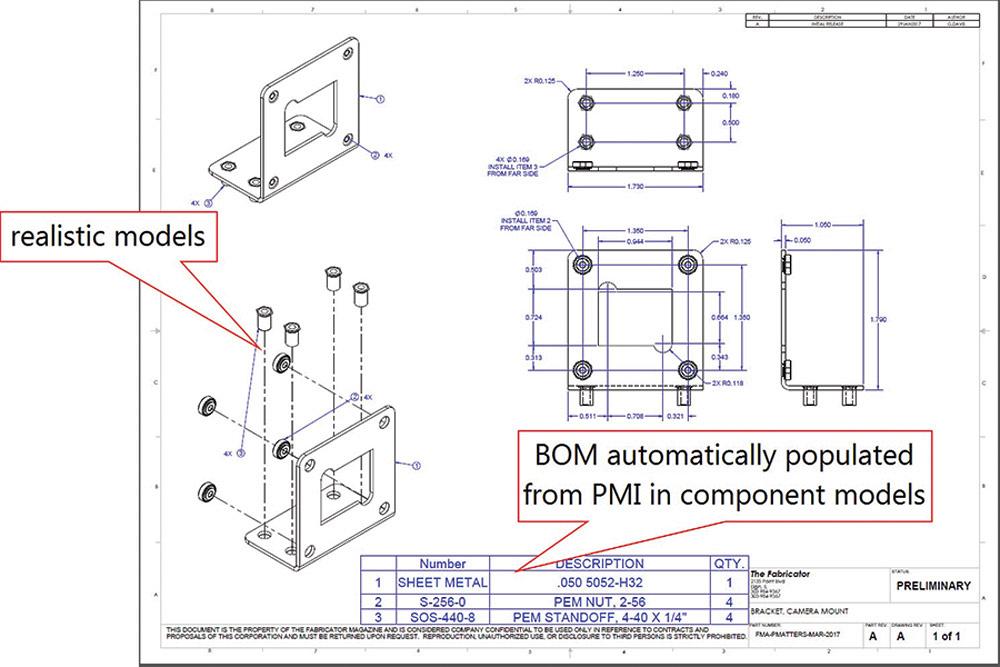
Figure 1b
The assembly from Figure 1a facilitates the production of this drawing. A library of detailed models with product manufacturing information (PMI) is part of this process.
Downloads are often available for 3-D models of off-the-shelf components. That is certainly the preferred “modeling” method.
Occasionally all that is available is a 2-D drawing. Figure 2a is a screen shot of a PDF available from www.jacomfg.com. We admire their products and thank them for the use of their catalog page as an example.
Figure 2b is a screen shot of the finished 2-D-to-3-D conversion. The underlying sketch has been shown to reveal the dimensions used. The dimension names (A, B, C, D, E, F, G, H, I, J) have been changed to match the catalog’s table of dimensions.
On the right side of the screen in Figure 2b, we see the Custom Properties tab. This is where the PMI has been filled in showing the description, part number, vendor, and source for the component.
To demonstrate the use of the Thread tool for speedy modeling of realistic threads, we offer the following multibody modeling technique:
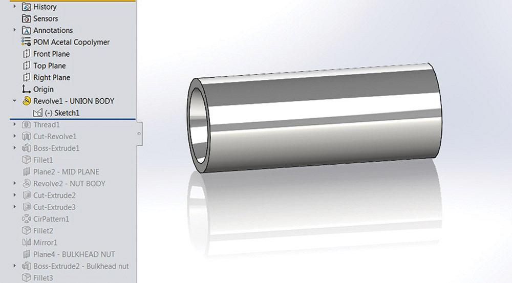
1. Figure 2c shows the first in a series of 6 CAD tip steps. A revolved body represents the through bore as well as the minor diameter of the threads. The sketch for that Revolve copies the catalog sketch, including unit of measure and dimension names.
Here’s a CAD tip: In some modeling projects it is helpful to use the download 2-D image as a sketch picture to help in scaling and approximating the sketch for the 3-D model.
Behind the scenes, the Revolve shown in Figure 2c uses selected contours in the sketch to omit the nut feature. Revolves have good rebuild times. Why not use an Extrude instead of Revolve? It takes more CPU because an extrude takes more steps to add the collet chamfers in the bore for the nuts.
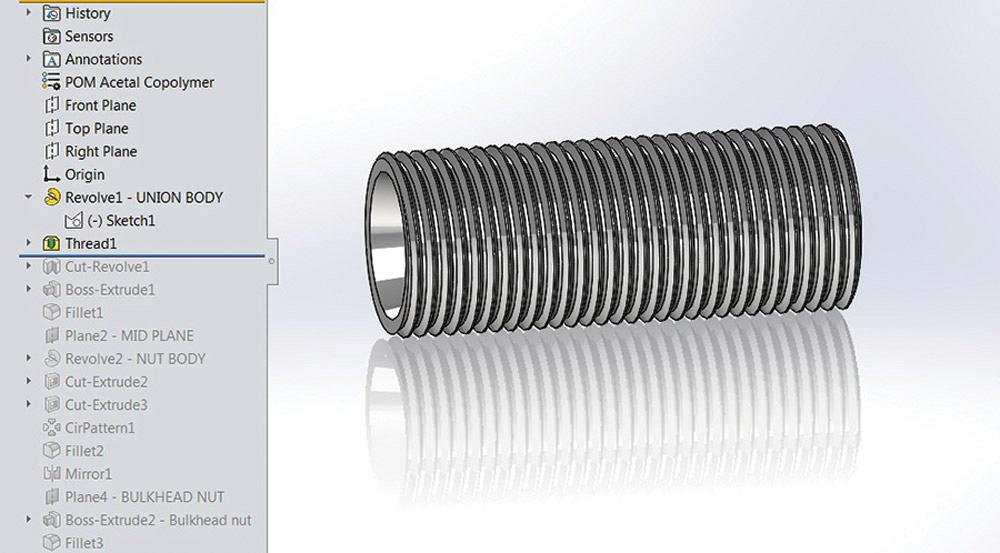
2. Figure 2d shows the convenient result of the Thread tool. In this example, the thread profile created by the Thread tool was located so that it automatically trimmed to the ends of both faces. This is very much like locating the profile for a Weldment.
Were this part to be manufactured, the thread detail would be slightly off. However, for quick modeling of a visual actor, the Thread tool is a handy modeling technique.
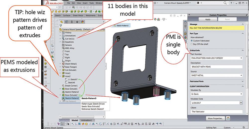
Figure 1c
Modeled for speed, multibodies include the sheet metal and the different types of machined hardware. This model explodes just like an assembly, but has all parts contained in a single CAD file.
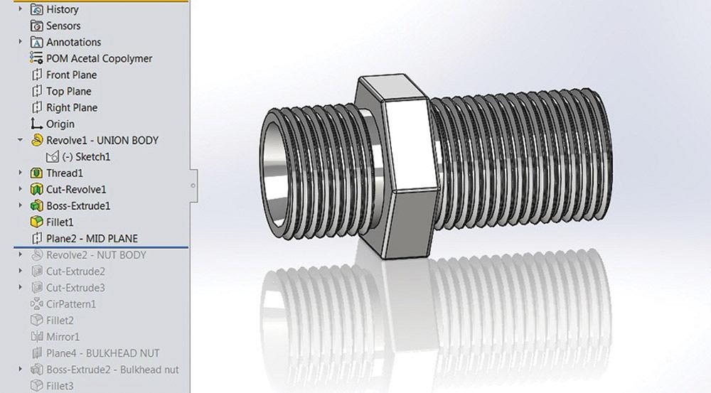
3. In Figure 2e several CAD operations have been completed. The results of a Cut Revolve for thread relief, the Extrude of a sketched hex for the nut body, and the addition of fillets to resemble the actual part are shown.
The trick of cutting the thread saves CAD labor but departs from real-world manufacturing. If that were a requirement, this model would have started with something that looked like hex bar stock instead of a threaded tube. Such a modeling operation would resemble actual lathe removal of material as well as separate modeling steps for the threaded ends.
Note in Figure 2e that a Mid Plane was created between the two ends of the tube. That plane comes into play as the models for the nuts are completed.
4. The multibody stage of modeling begins in Figure 2f. The nut body is separate from the model for the bore body. With the addition of a Move-Body feature, this separate nut body can be adjusted to resemble the actual clamped position in final assembly.
Here’s another CAD tip: The nut was created using Revolve and circular pattern of a single cut to resemble the familiar JACO style. Circular patterns are labor-savers.
As a side note, the detail showing thumb-reliefs is certainly optional. It does improve the visual accuracy of the model.
5. The CAD tip in Figure 2g is to mirror the nut body that was created in Figure 2f. The Mid Plane that was created in Figure 2e has finally come into play.
6. One function of this bulkhead fitting is adjustable clamping to match panel thickness. The stationary part of that clamp was modeled in Figure 2e. As hinted at in Figure 2h, the adjustable nut uses a reference plane. That plane is created at an offset distance from the stationary nut.
Here’s one more CAD tip: Adjust that plane’s offset distance to match the thickness of the panel in the target assembly.
We offer a download of the CAD models shown in these illustrations. It certainly took longer to type this than it did to actually model the project in 3-D. The resulting CAD file is a useful model for planning installation of plumbing. The best way to obtain these fittings is to buy them off-the-shelf.
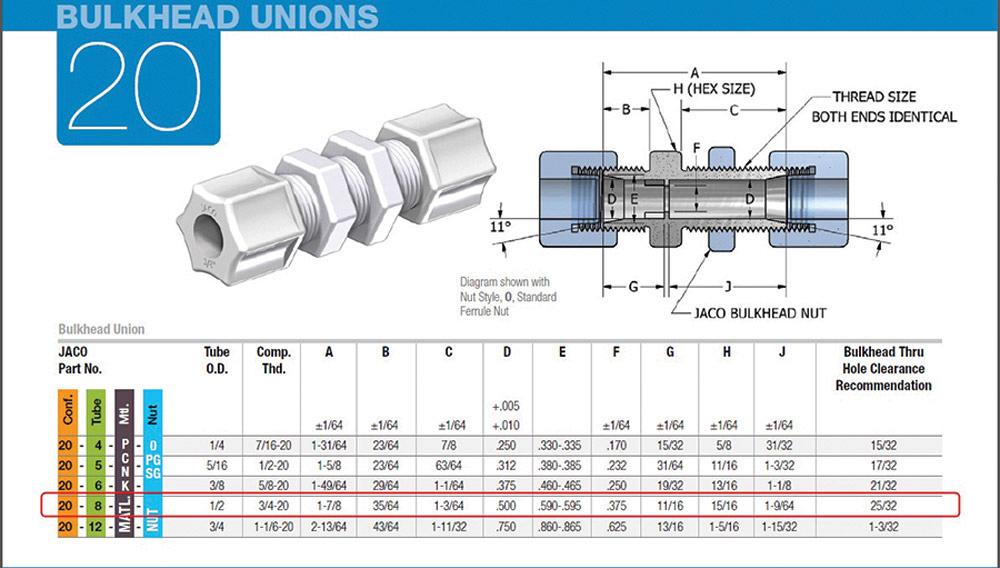
Figure 2a
An example of a catalog table of sizes for an off-the-shelf component is shown. (Screen shot courtesy of JACO Manufacturing Co.)
Gerald Davis uses CAD software to design and develop products for his clients at www.glddesigns.com. From 1984 to 2004 he owned and operated a job shop.
Gerald would love for you to send him your comments and questions. You are not alone, and the problems you face often are shared by others. Share the grief, and perhaps we will all share in the joy of finding answers. Please send your questions and comments to dand@thefabricator.com.


The Fabricator is North America's leading magazine for the metal forming and fabricating industry. The magazine delivers the news, technical articles, and case histories that enable fabricators to do their jobs more efficiently. The Fabricator has served the industry since 1970.
start your free subscription
Easily access valuable industry resources now with full access to the digital edition of The Fabricator.

Easily access valuable industry resources now with full access to the digital edition of The Welder.

Easily access valuable industry resources now with full access to the digital edition of The Tube and Pipe Journal.

Easily access valuable industry resources now with full access to the digital edition of The Fabricator en Español.
Seth Feldman of Iowa-based Wertzbaugher Services joins The Fabricator Podcast to offer his take as a Gen Zer...


