


Roll forming strategies for high-strength material
Modern technology addresses material challenges for metal fab shops
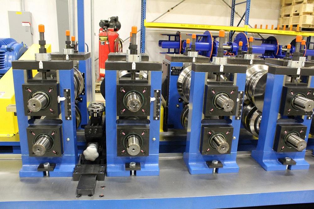
FIGURE 3. Side roll fixtures produce a better shape by easing the transition material undergoes from pass to pass.
Editor’s Note: The following is based on “Addressing Modern Day Materials in the Roll Forming Process,” presented at FABTECH 2022 in Atlanta, by Robert Taylor, COO of TEKFAB Inc.
For decades, roll forming equipment on shop floors across the continent have formed various conventional steels with low carbon content, high ductility, yield strengths between 36 and 50 KSI, and tensile strengths up to 80 KSI. In recent years, roll formers have needed to make more parts from high-strength materials: stainless steels with tensile strengths up to 95 KSI or high-strength/low-alloy (HSLA) material with tensile strengths up to 110 KSI.
HSLA materials have directionally sensitive properties; they form differently depending on where those forms are in relation to the material grain. They’re prone to cracking, especially when bent parallel to the grain. They exhibit greater toughness than standard materials and often require 25% more power to form (see Figure 1).
On top of all this, material properties can vary from one coil to the next, sometimes significantly. Due to material availability, roll formers sometimes have no choice but to use a substitute material, which might have material property variations outside the standard specifications.
Tensile strength specifications have evolved as well, especially for Grade 40, Grade 50, and similar steels. Such materials might be provided at the top end of their acceptable range rather than the minimum, which was typical in the past.
All this has made communication during the roll forming line build process more critical than ever. The experience often calls for comprehensive problem-solving—and it all starts with a good understanding of roll forming fundamentals.
Forming Fundamentals
Picture a strip of metal undergoing a pull test. Oversimplified, strain describes the actual length of elongation under load; stress describes the force applied to a particular area, and a stress-strain curve shows how those two phenomena interact as more stress and strain are applied. When stress and strain are applied at a certain level or below, you maintain uniform elongation. Past a certain level, the workpiece stretches to the point that it forms local necking—that is, the test strip gets thinner and thinner in a specific area until you get a fracture, at which point you can measure the total elongation at fracture (see Figure 2).
Yield strength is the maximum stress a material can endure before it starts to permanently deform. Tensile strength, on the other hand, is the maximum stress a material can endure, beyond which it fails and breaks. The range between yield and tensile strength typically helps define a material’s ductility. The narrower the range between yield and tensile, the less ductile (and more brittle) the metal is, which in roll forming can lead to cracking. (That said, some proprietary materials, like Domex, control the material chemistry very carefully to avoid this problem.)
Elastic deformation of a material under load is recoverable when the load is removed. Plastic deformation under load is not recoverable when the load is removed; that is, the material takes a permanent set. In either case, sheet metal bending must account for springback, or the geometric change of the part when it’s released from the forces of a forming tool. The forming tools, or rolls, are generally designed with adjustments that compensate for this effect.
Plastic deformation of the material leads to work hardening, increasing its yield strength. Also called strain hardening, the phenomenon in roll forming can cause material to crack, especially in the outside corners of roll formed shapes.

FIGURE 1. High-strength material often requires special roll tools, such as this side angle pass that contacts the inside radius of the workpiece directly during forming.
The greater its tensile strength, the greater load the material requires to get it into the plastic zone. This is why high-tensile materials have greater springback. It’s also why sufficient overbend must be designed into the roll tooling for the material being processed.
Forming Defects
Even the most advanced roll forming lines won’t perform well if operators aren’t trained on the basics. Setup procedures need to be well documented and repeatable. Tools need to be in good condition. And machines need to be well maintained, with shafts and bearings in good condition and shaft shoulders properly aligned.
Even when it’s conventional steel, a strip’s actual state of stress in a roll forming pass is much more complex than a simple bend. Controlling those stresses become even more challenging with high-strength material. Overall, roll forming puts a metal strip into a complicated state of stress, both transversely and longitudinally. After the shape exits the roll tools, these internal stresses can act on the part and cause it to assume a nonstraight shape.
Different portions of the profile travel through a roll form mill along different paths. Those path length differences cause stresses in the material along the length of the part. If material yields in one area differently from another, straightness issues arise, such as with camber (side to side) or bow (up or down) defects. A closely related defect, twist involves rotation of the part along its length. Like camber and bow, twist occurs when yielding on one strip edge or location is more than another.
Another common defect, end flare occurs as a result of the stresses put into the material as it transitions from one pass to the next. Deformation can occur on the first or second cut as the part exits the mill. In most cases, one end will flare in while the opposite end will flare out.
A good roll design can minimize end flare, as can the addition of antiflare fixtures at the end of the roll former. The fixtures aim to equalize the stresses in the profile of the formed part.
Length and Feature Tolerances
Defects with part length and feature locations sometimes happen because of problems with the length control system, which controls the punching and shearing of the part. Sometimes, though, these defects occur because of when the punching and cutting process takes place.
In some roll forming programs, parts are prepunched, roll formed, then cut off. Such sequences can amplify the effect of material variation. The length control system might position the strip in the perfect location for the prepunch station to create the holes. But as the sheet undergoes roll forming, it stretches.
Material property variations, especially in yield strength, can affect how much the material stretches at a given point. This can make it difficult to produce precise parts. Operators can make a lot of scrap dialing in the part tolerances, but the next coil might require entirely different settings. In many cases, punching and cutting the critical features after roll forming (postpunching) can eliminate such variation. Moreover, a line with no prepunching, just postpunching and cutoff, also has less material in process, which can help reduce scrap from line stoppages and when making adjustments.
Designing Equipment for Difficult Material
A lot of older systems struggle to make parts with steel that’s technically within its rated gauge range. As they say, today’s 12 ga. is yesterday’s 10 ga. The issue comes not only from the tensile strength of the steel but also from the condition or design of the equipment. So, what goes into designing a line to form challenging material?
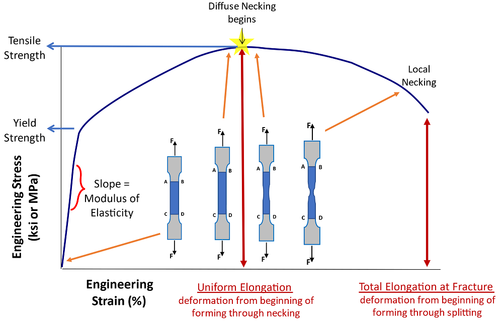
FIGURE 2. As this stress-strain curve shows, uniform elongations continue up to a certain point, until local necking begins, where the strip gets thinner in a specific area.
Sizing the Line. If a roll form line is already undersized for standard-tensile-strength materials, then running high-strength strip will introduce even more problems. Torque limitations will become immediately apparent. Roll form mills need larger, more rigid shafts, uprights, and bearings. They also need greater horsepower.
Part Length Control. It can be difficult to dial in a roll forming application involving high-strength material, but closed-loop control can help. The newest control technology helps produce much more accurate parts at higher speeds. With a properly designed rolling mill, closed-loop controls help compensate for less-than-ideal material and still produce parts with great accuracy. Today’s lines can have closed-loop control of precutting, postpunching, and cutoff, all working in concert to put features in the part accurately and repeatedly.
Adjustment Aids. Roll forming high-strength material can require some fine-tuning, so adjustment aids such as digital readouts and single-point adjustment systems can help. They not only increase efficiency, but they also allow for more repeatable setups. Defects like flare, bow, and twist tend to be more pronounced in high-strength material, and the entire setup will likely require more passes or side roll fixtures. If setups aren’t dialed in, or if material properties vary more than expected, cracking can emerge, especially on the outside of sharp bends.
Tools and Fixtures. Material with high yield and tensile strength requires greater overbend to set the bends to the required shape, and roll tools need to account for this. High-strength material tends to break down corner radii on roll tooling, so large corner radii are usually preferred. For especially challenging setups, tooling designers likely will rely on finite element analysis to design the rolls properly.
Successfully roll forming high-strength materials involves controlling the forming of inside corners and easing the transition of the material from pass to pass. Air bending—when neither upper nor lower rolls contact the surface of the inside bend radius—usually isn’t successful on high-strength material.
Tools like side angle passes (angled rolls that contact the inside of a bend directly, as shown in Figure 1) and side roll fixtures help produce a better shape (see Figure 3). Again, it’s all about securing and tightly controlling how the strip forms as it progresses from one roll station to the next.
Punching and Cutoff. Stations with punching and cutoff presses must have sufficient tonnage ratings (see Figure 4). Air presses or old mechanical presses probably are not up to the task.
Regardless, tools that punch and cut high-strength material won’t last as long and will require more frequent service.
Long Parts, Minimal Camber
One manufacturer was roll forming 7-ga. and 12-ga. steel with tensile strength above 100 KSI. The line included a rafted roll former with multiple rafts that sped the changeover between a number of different shapes. The roll forming line was producing a good profile, well within industry-standard straightness tolerances of 0.015 in. per foot of length, both for bowing and camber. Unfortunately, the application demanded extraordinarily tight camber control—less than 0.25 in. on a 40-ft.-long part. The components were part of a walking floor system, and if they weren’t perfectly straight, they would bind on the supports.
The system had a traditional straightener after the last roll-tooling pass. The shallow part shapes made it easy to straighten for bowing (up and down). To straighten for camber (side to side), the system had very little material to push against. Effectively, the roll forming machine was trying to straighten a very high-tensile-strength part the hard way (that is, along the longer axis).
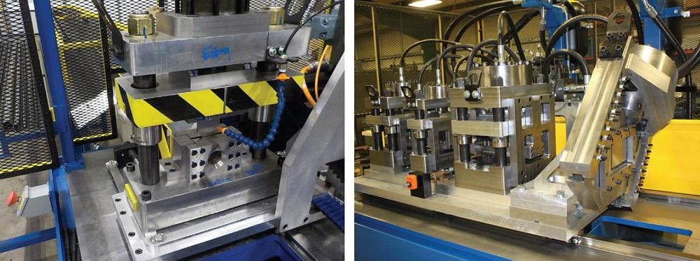
FIGURE 4. Tonnage ratings must be sufficient for presses used for punching and cutoffs.
Some troubleshooting was in order. The material coming off the coil had camber, and the roll-formed part came out with the same amount of camber. The reality was that this wasn’t a roll forming issue. It was a material issue, and this called for special equipment—a decambering unit that processed the strip off the coil before entering the roll forming mill (see Figure 5). The unit essentially produced straight strip that could then be formed into straight finished product that adhered to stringent customer standards.
High Standards for High Strength
Most manufacturers are pushing for greater speeds to improve profits, but the reality is that many “old-school” roll forming lines simply aren’t capable of producing parts with the kind of tight feature tolerances required today, especially in high-strength material. Those old-school lines are becoming obsolete.
Today’s roll forming lines need to be rigid, so that equipment adjustments to move the material don’t “flex” the machines. This again calls for larger shafts and bearings. Modern lines also need to be repeatable, hence the need for digital readouts.
Material testing has become more important too, so that material properties are known before the production run. Combine that with well-maintained equipment and good recordkeeping, and a roll forming line can be productive for years, even when forming material with little room for error.
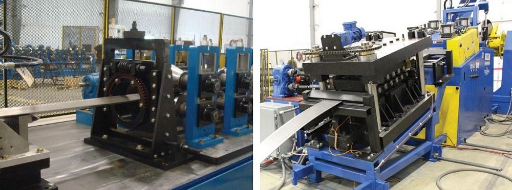
FIGURE 5. The decambering unit on the right straightened material before it was roll formed, ensuring the finished 40-ft. product adhered to stringent straightness standards.
About the Publication
subscribe now

The Fabricator is North America's leading magazine for the metal forming and fabricating industry. The magazine delivers the news, technical articles, and case histories that enable fabricators to do their jobs more efficiently. The Fabricator has served the industry since 1970.
start your free subscription- Stay connected from anywhere

Easily access valuable industry resources now with full access to the digital edition of The Fabricator.

Easily access valuable industry resources now with full access to the digital edition of The Welder.

Easily access valuable industry resources now with full access to the digital edition of The Tube and Pipe Journal.

Easily access valuable industry resources now with full access to the digital edition of The Fabricator en Español.
- Podcasting

In this episode of The Fabricator Podcast, Caleb Chamberlain, co-founder and CEO of OSH Cut, discusses his company’s...
- Trending Articles
1
Tips for creating sheet metal tubes with perforations

2
Are two heads better than one in fiber laser cutting?

3
Supporting the metal fabricating industry through FMA

4
JM Steel triples capacity for solar energy projects at Pennsylvania facility

5
Omco Solar opens second Alabama manufacturing facility
