


Communications Manager
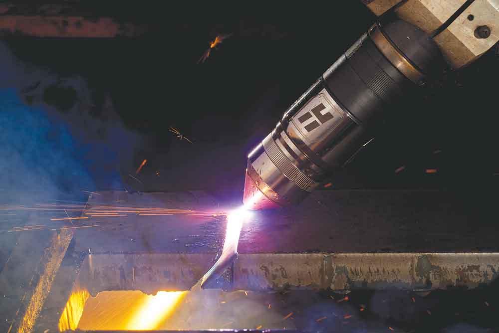
Do your plasma-cut parts have excessive dross or out-of-round holes? Are holes warped? Having trouble welding those edges downstream? These time-tested tips can help metal fabricators. Getty Images
Pair a high-quality plasma power supply with the right cutting table or system and it is possible to cut parts with smooth edges and little to no angularity. Still, fabricators are bound to encounter less-than-satisfactory cut quality from time to time. Here’s a look at the most common cut quality challenges and the steps needed to get back on track.
By far the most common cut quality issue fabricators face is dross. Though it is relatively easy to remove the excess metal that solidifies along the top and bottom edge of the part, it still adds work. When someone has to perform a secondary operation like grinding, chipping, or sanding, it is often to remove dross.
Dross occurs for a number of reasons. Cut speed, either too slow or too fast, is a common culprit, but it is far from the only one. The distance between the torch and material being cut, along with amperage, voltage, and consumable condition, all affect dross too. There is also the issue of the material being cut—its thickness and type, grade, chemical composition, surface condition, flatness (or lack thereof), and temperature changes while cutting all impact the process. In total, more than a dozen factors are in play, though, fortunately, only three are critical: cut speed, amperage, and the standoff distance.
When the cut speed is too slow, the plasma arc will look for more material to cut. The arc column grows in diameter, widening the kerf to a point where the high-velocity portion of the plasma jet no longer blows the molten metal away from the cut. Instead, that metal accumulates along the bottom edge of the plate, forming low-speed dross. Cutting at too high an amperage or too low a standoff can also cause low-speed dross as both those changes cause more energy from the plasma arc to contact a given area of the metal.
The solution is obvious then: cut faster. Unfortunately, this brings its own set of challenges. If the cut speed is too fast, the arc can’t keep up. It falls, or lags, behind the torch, leaving a small, hard bead of uncut material along the bottom of the plate. In many ways, this high-speed dross is worse than its low-speed counterpart as it is harder, usually requiring extensive machining to remove.
At extremely high speeds the arc can even become unstable. It will begin to vibrate up and down, causing a rooster tail of sparks and molten material. At these speeds the arc may fail to cut through the metal and can also stop. Too low an amperage or too high a standoff can also cause high-speed dross since both changes reduce the amount of energy from the arc.
In addition to low- and high-speed dross is a third type called top spatter dross. This happens when resolidified metal sprays along the top of the cut piece. It is usually very easy to remove. A worn nozzle, excessive cutting speed, or a high standoff is usually the cause. It is caused by the swirling flow of the plasma jet, which at a certain angle flings molten material out in front of the kerf rather than down through it.
Between the two extremes of low- and high-speed dross is a “just right” window, officially called the dross-free zone. This is key to minimizing secondary operations on plasma-cut pieces. Your window will vary. Generally, when using nitrogen or air as the plasma gas on carbon steel, you’ll find your dross-free window is fairly small. Fabricators cutting with oxygen plasma will have a little more leeway. Although it isn’t always easy to find this optimum cutting speed, there are a couple of things you can do.
Make several cuts at various cutting speeds and choose the speed that produces the cleanest cut. Lag lines (small ridges in the surface of the cut) are a good way to judge your cutting speed. If you are cutting too slow, you will see lag lines that are perpendicular to the plane of the plate. If cutting too fast, you will see slanted S-shaped lag lines that run parallel to the plate along the bottom edge.
Also, watch the arc (wearing the right eye protection) during the cut and dynamically change the speed to produce the optimum arc characteristics. To do this, observe the angle of the arc as it exits the bottom of the workpiece. If you are cutting with air plasma, the arc should be vertical as it exits the bottom of the cut. With nitrogen or argon/hydrogen, a slight trailing arc is best, while a slight leading arc is best with oxygen.
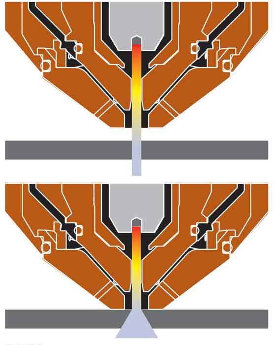
Figure 1
The distance between the torch and workpiece is critical. When the torch is properly positioned (top), the arc will remain narrow. If it’s too close (bottom) or far from the plate, the arc will widen, creating a part with an exaggerated angle.
A final tip when it comes to dross: Refer to the owner’s manual that came with your cutting system. Plasma process engineers spend months in a lab experimenting with various parameters to create comprehensive cut charts listing recommended cut speeds, cut heights, and amperages for many material types and thicknesses. Always start with these set points and adjust from there in 10% increments, both up and down.
Cutting parts with as little edge angularity as possible is another challenge for fabricators. This happens because a plasma arc isn’t perfectly straight. This means any metal cut with plasma will have some degree of angularity, but there are ways to minimize it.
One way is to match your consumables and power level to the material thickness you need to cut, keeping in mind that lower amperage levels and slower cut speeds will give you less angularity. Also, carefully inspect your consumables, especially the nozzle and shield, for any damage. Even a small ding or nick can affect cut quality. Finally, make sure your torch is the right distance from the plate, after the pierce and throughout the entire cut (see Figure 1).
Here are a few things you can do to prevent winding up with warped material and parts. First, program your CAM software to create cut paths that control the heat input by allowing sections to cool before cutting adjacent parts. This is especially useful when cutting very thin material.
Next, use the lowest possible amperage and corresponding consumables at the fastest possible cut speed for the material thickness. Finally, if you have a water table, keep the water in contact with the material. Just keep in mind that on many materials, water can affect edge smoothness and, in some cases, edge hardness.
Any material cut with a plasma arc will show metallurgical effects on the edges. After all, you are introducing an extremely large amount of heat to the metal. Fortunately, you can lessen these effects through gas selection.
If you are cutting carbon steel, using oxygen for both your plasma and shield gas will give you the best edge metallurgy. An oxygen/oxygen process is especially beneficial when cutting holes smaller than 2.5 inches in diameter. In fact, the metallurgy effects are so minor, this process is often suitable for thread tapping.
In addition, parts cut with oxygen are 100% weldable and machinable, and they rarely crack during forming operations. Air or nitrogen plasma does cause some edge hardening and nitriding on most steels, which can make edges brittle and create porosity during some welding processes. Fortunately, this nitride layer is generally thin, between 0.006 and 0.010 in. thick, and easy to remove.
If you need to cut stainless, a mix of gases is recommended. It is possible to cut stainless steel less than 1/4 in. thick with a very pure edge using a 5% hydrogen/95% nitrogen mix for the plasma gas. Thicker stainless sections often do better when cut using a 35% hydrogen/65% argon mix. No matter the thickness, a nitrogen shield gas is recommended. Another option is to cut stainless underwater using nitrogen for both the plasma and shield gas, eliminating the oxide layer that forms when cutting in ambient air.
To recap, use oxygen, if your system supports it, for the best edge metallurgy on carbon steel. For stainless, use a hydrogen/nitrogen mix on material less than 1/4 in. and a hydrogen/argon mix on material thicker than that; always use nitrogen as your shield gas, regardless of thickness.
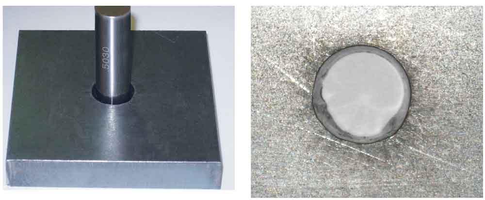
Figure 2
Hole cutting can require some trial and error as operators struggle to prevent out-of-round or tapered holes as well as holes with excess metal along the inside radius.
Though the previous tips will improve cut quality on most parts and shapes, hole cutting will require a bit more work. The rule of thumb is that the hole diameter should be no smaller than the thickness of the plate, so if you are cutting 1/2-in.-thick plate, you’ll want to cut holes that are 1/2 in. in diameter or larger. However, even when doing this, operators often struggle with out-of-round or tapered holes, in which the top of the hole is larger than the bottom (see Figure 2).
Air plasma always will produce a hole with some natural, albeit very little, taper because of the lagging arc angle from the plasma jet. High-definition and X-definition plasma systems will produce a nearly nonexistent taper.
As a general best practice when plasma cutting holes, pierce the plate at the recommended cut height and use a pierce delay time. Your plasma owner’s manual usually will tell you how long a delay is needed. This will prevent or at least decrease molten metal blowback on your shield and nozzle.
A second tip is to play with the lead-in to your hole. Start your lead-in close to the center of the hole rather than the radius. This will ensure the divot that forms during piercing will occur in the metal being cut away rather than the edge of your hole. Starting in the center has a second advantage in that it gives the arc more time to stabilize and gives the torch height control more time to index down to the cut height before reaching the radius. Though most machines can produce excellent holes when lead-in shapes are straight and perpendicular to the hole, more sluggish machines will benefit from the use of a radial or curved lead-in (see Figure 3).
Ideally, you want the arc to stop or shut off at or beyond the 360-degree lead-in kerf. Some software can shut off the plasma arc at the lead-in kerf crossing while keeping the motion active, which is the best way to cut holes as it allows for a smoother end-of-cut transition and a very small divot when the arc turns off.
Cut speed should be about 60% of the speed you use to cut the outside contour of the part. This cut speed adjustment will give you some low-speed dross, but the trade-off is worth it since it will minimize hole taper. When cutting holes less than 11/4 in. in diameter, it is best to disable the arc voltage control and voltage height correction and instead enable the pierce height and the indexing-to-cut height feature. This is recommended because the slower speed used for cutting holes will cause the arc voltage control to move the torch too close to the plate.
These tips are a good starting point. Still, as mentioned earlier, your specific system will affect your end results to a large degree. This is because the process capability among plasma and table manufacturers varies widely. Differences in the type of torch height control, CAM software, along with table motion and acceleration capabilities can really impact your end result. Even so, these tips and suggestions are sure to improve cut quality and hole shape for anyone using plasma, regardless of type—air, conventional, high-definition, X-definition—or brand.
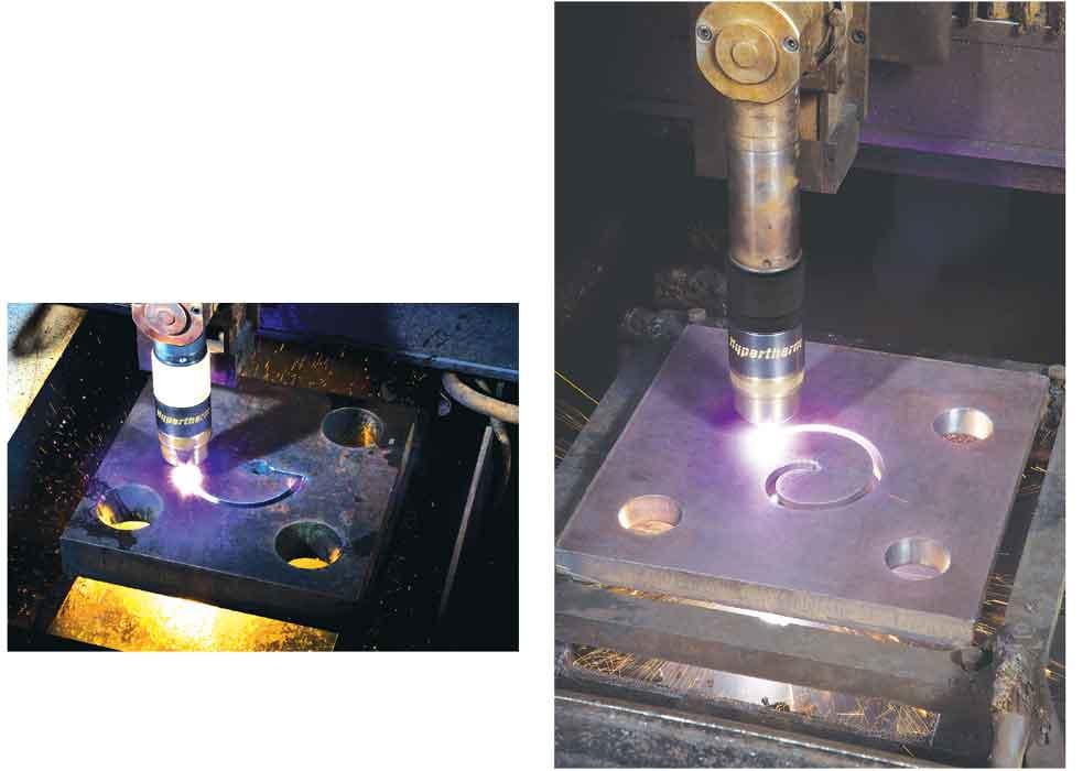
Figure 3
Though a perpendicular lead-in (left) works with most machines, a curved lead-in (right) is helpful when using a slower machine.


The Fabricator is North America's leading magazine for the metal forming and fabricating industry. The magazine delivers the news, technical articles, and case histories that enable fabricators to do their jobs more efficiently. The Fabricator has served the industry since 1970.
start your free subscription
Easily access valuable industry resources now with full access to the digital edition of The Fabricator.

Easily access valuable industry resources now with full access to the digital edition of The Welder.

Easily access valuable industry resources now with full access to the digital edition of The Tube and Pipe Journal.

Easily access valuable industry resources now with full access to the digital edition of The Fabricator en Español.
In this episode of The Fabricator Podcast, Caleb Chamberlain, co-founder and CEO of OSH Cut, discusses his company’s...


