


Senior Editor
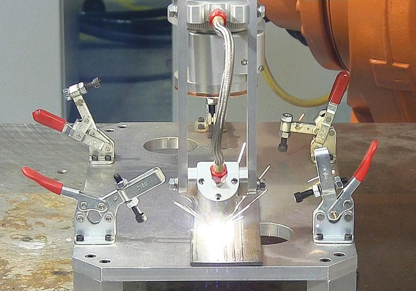
A fiber laser head welds with real-time weld depth monitoring using inline coherent imaging, or ICI.
Many variables affect the quality of a laser weld. The laser power needs to remain stable and the optics must remain as clean as possible to avoid problems with the beam such as focus shift, which can change the spot size and, in turn, affect the weld quality.
These all are optical issues. “But there are nonoptical issues too that relate to weld quality. And the No. 1 issue relates to weld penetration.”
So said Tom Kugler, fiber systems manager at Novi, Mich.-based Laser Mechanisms, who earlier this year gave a presentation at the Advanced Laser Applications Workshop (www.alawlaser.org ) on a monitoring technology that aims to address this penetration variable directly. It’s called inline coherent imaging, or ICI.
Some laser welding applications entail operations that have sufficient controls—including consistent workpiece geometry and makeup, solid fixturing, and proven welding procedures—that make real-time monitoring unnecessary. But other applications, particularly mission-critical or parts with high value, do require some type of monitoring to catch problems. These controls provide a record that proves that welding was performed according to the requirements.
One option has been to use process monitoring that interprets different wavelengths of light (infrared, laser wavelength, and ultraviolet) being directed back from the keyhole welding process. In laser welding, the keyhole itself is created and maintained by liquid metal on the surface that has vaporized. “As the laser beam superheats the surface of the keyhole, it causes liquid metal to vaporize,” Kugler said. “The recoil of that gas expulsion is what pushes the liquid [metal] back, forming the keyhole and keeping the keyhole open. It’s extremely hot, and if you don’t have that kind of heat, you don’t have a keyhole weld. The ultraviolet light that’s emitted is created because of that high heat, and the size of the keyhole and its intensity can be reflected in the UV signal coming back.”
Meanwhile, the solidifying metal radiates a lot of infrared energy, so monitoring the IR wavelength from the weld gives an idea of the melt pool. “If you have a larger melt zone, you’re going to have a larger infrared signal,” Kugler said.
He added that such monitoring systems usually require a lot of test welds.
Technicians destructively test those welds by cutting a weld cross section; they match that weld with the data from the weld monitor to determine where to set the monitor limits for each wavelength signal.
If the monitor detects the signature within the test ranges, all is probably well. If it detects signal levels outside of this range, there may be a problem with the weld.
One problem with all this, Kugler said, is that the test welds require time and money. These systems also don’t measure weld penetration directly, but instead through inference. That is, a technician can infer there’s a problem with weld penetration if the system detects signal levels outside of the defined limits.
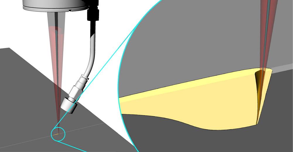
Following the beam path, ICI indicates weld penetration by measuring the distance to the bottom of the keyhole in real time.
This is where ICI could help fill a need. The technology works by sending a sensing beam—basically just one wavelength of light—to the bottom of the keyhole to measure the depth and determine weld penetration. It can also send the beam just behind the welding beam to measure the solidified weld topography, detecting surface porosity as well as the weld surface shape, be it convex or concave. Also, the beam can be sent just in front of the keyhole to seam-track and auto-focus.
“The signal level is related to a lot of factors, including the incident beam energy,” Kugler said. “This means you have a very high gain level, which means you need only a few photons per million in the sensing beam to get information back [to the monitoring system] to measure the distance to the bottom of the keyhole.” He added that because the measurement beam takes the same path as the laser beam (hence the name “inline” coherent imaging), having access to the weld joint isn’t an issue.
The idea behind ICI actually doesn’t come from manufacturing. It instead has origins in the medical field, where it was initially developed to overcome challenges when using lasers to ablate bone tissue. Surgeons needed a way to ablate bone to a specific topography, which isn’t a huge challenge if the material makeup is consistent. Of course, bone isn’t consistent at all. What surgeons needed was a way for the laser power and beam characteristics to adjust on-the-fly—and this is where the ICI technology came into play. The signal gave the system real-time depth measurement; that information, such as power and travel speed, fed back to the laser control, which adjusted on-the-fly to ablate the bone material to the desired topography.
Kingston, Ont.-based Laser Depth Dynamics Inc. developed this technology for laser keyhole welding. The monitoring hardware can attach various laser welding heads, including the FiberWELD® head from Laser Mechanisms.
While on-the-fly laser adjustment is possible in manufacturing applications, Kugler mentioned that most companies use the technology to track and record achieved weld penetration, not to change laser welding parameters on-the-fly. If the system detects poor weld characteristics, engineers then correct parameters after the fact.
Like other in-process monitoring systems, ICI doesn’t detect the consistency of the weld interior, such as porosity or cracking. For that data, welding engineers still need to turn to nondestructive examination techniques like radiography and ultrasonic testing.
Regardless, Kugler said that the big benefit is the fact that, because ICI measures the actual depth of the weld as it’s being made, the system doesn’t require technicians to perform periodic destructive testing on a weld cross section to confirm that the target data from the weld monitor correlates with a good weld.
“We have customers who spend a lot of money every year on destructive testing,” Kugler said. “These are parts that were welded and get destroyed. Usually it’s good product, and they’ve put a lot of money into it up to that point. [After destructive testing], all that added value is gone.”
Images courtesy of Laser Mechanisms Inc., 25325 Regency Drive, Novi, MI 48375, 248-474-9480, www.lasermech.com.
Laser Depth Dynamics Inc., 2 Gore St., Kingston, ON K7L 2L1, Canada, 613-887-2331, www.laserdepth.com
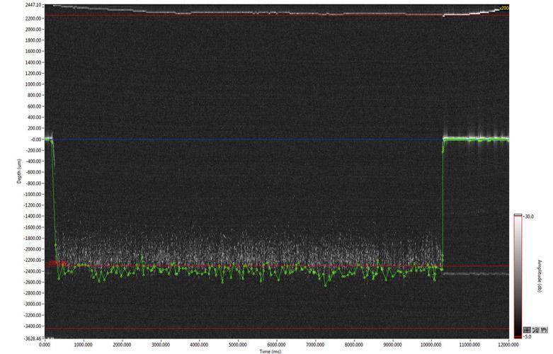
This data shows excellent weld penetration in 2.3-mm-thick material.


The Fabricator is North America's leading magazine for the metal forming and fabricating industry. The magazine delivers the news, technical articles, and case histories that enable fabricators to do their jobs more efficiently. The Fabricator has served the industry since 1970.
start your free subscription
Easily access valuable industry resources now with full access to the digital edition of The Fabricator.

Easily access valuable industry resources now with full access to the digital edition of The Welder.

Easily access valuable industry resources now with full access to the digital edition of The Tube and Pipe Journal.

Easily access valuable industry resources now with full access to the digital edition of The Fabricator en Español.
In this episode of The Fabricator Podcast, Caleb Chamberlain, co-founder and CEO of OSH Cut, discusses his company’s...


