


Senior Editor
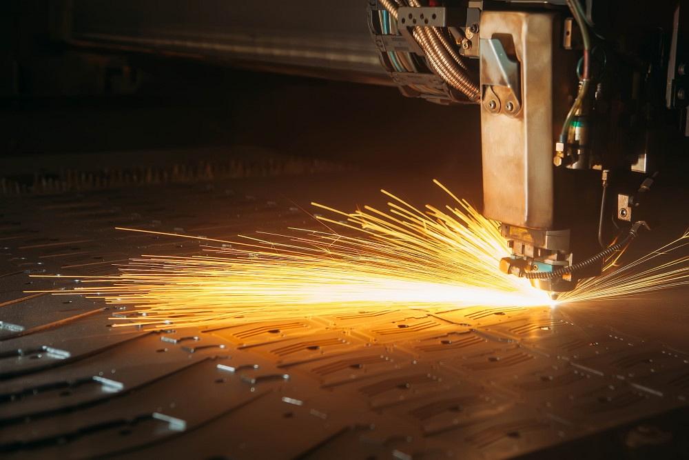
Laser cutting has become extraordinarily productive—if the head doesn’t halt or crash, of course. Considering how productive the latest laser cutting technology is, smart nesting has become more important than ever for metal fabrication shops. o_shumilova / iStock / Getty Images Plus
The fiber laser has made the primary cutting operation at most metal fabricators extraordinarily productive—until a part tips and causes a head to stop or crash. To prevent this starts with knowing some nesting fundamentals and, most critically, how decisions in nesting and laser programming affect all the manufacturing steps that follow.
Years ago, many machine providers and software vendors focused on transitioning operators from punch presses to the flying-optic lasers. Because the punch moves the sheet, everything needs to be tabbed in place, at least until they’re evacuated down a chute or lifted by suction cups on an automated part removal system. Otherwise, parts don’t fall out of a nest until operators snap or shake them out. When shops jumped to the flying optic lasers, sheets no longer moved, and many parts that were punched with microtabs no longer needed them. Of course, such lasers introduced a new variable: the slat position.
As Mike Boggs, vice president of sales and marketing at Striker Systems, put it, training starts with the fundamentals, especially now that so many experienced people are retiring. “Going back to basics, the primary cause of tip-ups is the size and shape of the part relative to its position on the support slats.”
“Ultimately, the position of these parts on the nest and where parts are in relation to the slats on the machine really matter,” said Doug Wood, sales director, Sheet Metal Solutions North America at Hexagon, maker of Radan software.
Slats generally are placed 2 to 3 in. apart, depending on the model of the machine. So, if a part (or slug from an internal feature) has at least one dimension less than 6 in., it has the potential to tip. Picture a rectangular part that’s 5 in. If the nest has that piece placed such that it rests on just one slat, that piece just might tip after the laser cuts its profile.
This is where slug-destruct sequences can help. Why risk a slug getting jammed and tipping up when it can be cut in little pieces and fall safely away? “When you do parts with larger cutouts [which have the potential for tipping], destroying that slug and getting it to fall through the slats can be beneficial,” Wood said.
Most slats consist of tips or “teeth” that support the work. Certain part geometries could end up tipping into the “V” of the slat. The slat condition has an effect here too. If a slat hasn’t been cleaned, the sheet can actually sit higher on certain slat teeth, opening the door for more process instability.
Smaller parts can tip, but larger parts—especially those that are long and thin—can bow upward and throw a wrench into process stability. Material touted as being “laser flat” ideally should have equalized stresses such that, when a part is cut in the optimal way (to control the effects of heat, for instance), it doesn’t bow. Whether this happens or not depends on the material on the laser cutting bed. If the distortion level is unknown, programmers might opt to tab parts in place.
These days, software can automatically detect and rotate parts so that the longest dimension is oriented perpendicular to the slats. Programmers also can set different tabbing strategies for different part sizes; a very small part might require just one tab, while larger parts up to a certain dimension require progressively more. Beyond a certain dimension, software won’t place any tab at all.
“These rules just set an intelligent hierarchy based on the part position on the table in relation to the support slats,” Boggs said.
Previously cut parts and slugs (on the left) tip up. This is why the head traverses away from those previously cut pieces or, if needed, raises to run “air cover,” keeping a safe distance away from those tip-ups. Phuchit/iStock /Getty Images Plus
“Tab placement can depend on cosmetic concerns as well,” Wood added. “With all this, you can have the software automatically tab based on the X and Y dimensions of the component, but you can force certain tab placements when the need arises.”
The size of those tabs can be controlled for various materials as well as different scenarios around assist gas—particularly when it comes to high-pressure nitrogen assist gas, the turbulence from which can cause cut parts to tip and move far more than when cutting with oxygen. “[Turbulence from high-pressure nitrogen cutting] can mean a shop will need either larger or more tabs, based on the size of the part,” Boggs said.
Tab placement can vary depending on the job requirements and the best practices at a particular company, Boggs said. For instance, some operations might choose to tab parts directly on the corners, while others prefer tabs on straight edges and, if a corner needs something for stability, put a tab several thousands of an inch away from the actual corner. It all depends on what benefits downstream operations and the part’s ultimate fit and function.
Tab geometry can change depending on material thickness and grade, of course, but it can also change based on what operations a part will undergo downstream. Those tab geometries affect how they break away from the part.
At the laser offloading area, operators might shake parts out of a nest before running them through a flat-part deburring machine. Microtabs typically leave a burr on the part and a divot in the skeleton. This assumes that a fabricator will want to deburr the piece to create a perfectly flat edge.
But does every part need a perfectly flat edge? What about edges that will be hidden within an assembly or covered by a weld? In these cases, shops might choose to skip deburring and send the parts directly to forming. Unfortunately, because the burr sticks out slightly, when the brake operator gauges the part for the bend, it rocks ever so slightly against the backgauge finger. That causes a bend line misalignment that, in a shop fabricating to tight tolerances, can snowball into a host of other problems.
In this case, Boggs said, a programmer could choose to create what he called a “burrless tab,” with a geometry that breaks differently, creating an ever-so-slight divot on the part edge. “The programmer can control how deep this divot is,” Boggs said, “and it just might be a few thousands deep, so it won’t make a difference to the final fit and function of the part.” He added that where this makes sense depends on the part requirements.
Consider robotic and Cartesian systems that use suction-cup grippers to remove and stack parts. “Some parts are so small,” Boggs said, “that they can’t be individually lifted out of a nest. We might create within a nest a kind of mini-nest of a group of tabbed-in-place parts.”
Cut nests that are transported back to tower shelves might require more tabbing to ensure part stability. Boggs gave another example of fork systems that removed tabbed-in nests of very large parts in which more microtabs are necessary around the part perimeter, just to prevent long or large pieces from sagging and getting caught between the individual fork tines.
Skeleton-destruct sequences can make life easier for those at the denesting station and skeleton disposal. When the laser cuts through certain skeleton web sections, those removing parts now can quickly dispose smaller portions of the skeleton. Such skeleton-destruct sequences do, however, require some attention to detail.
“This is set up to account for the specific machine a fabricator uses,” Boggs said. For instance, to destroy the skeleton, the head might travel near the edge of or slightly off a sheet (which can vary, depending on the size tolerances of the sheet on the cutting bed). In this case, the cutting head needs to be told to lock itself in place, lest it move downward to “hunt” for a cutting surface that isn’t there. Boggs emphasized, though, that the necessary steps to make this happen vary with the machine being used.
Sources emphasized that when and where skeleton-destruct sequences make sense depends on how sheets move through a laser system, including the part offloading strategy. Some scenarios might benefit from skeleton-destructs, while others might need the stability of a skeleton with securely tabbed-in-place parts.
Some level of risk exists any time a cutting head needs to traverse over previously cut material. Theoretically, even if tip-ups run rampant throughout a nest, the cutting head won’t crash if it never passes over previously cut parts.
“You need to base your part lead-in and lead-outs so they’re in the optimal location in terms of machine travel and cutting speeds, but also logistics,” Wood said. “It’s about ensuring you’re not traversing over components once they’ve been cut. You can also run ‘air cover’ with feature avoidance. If the laser is in an area where it can’t get out of [without traversing over previously cut parts], the head can lift and traverse safely to the next location.”
Say a cutting head goes from the lead-out of one part immediately toward the nearest lead-in of the next part. That sounds logical and efficient, but what if moving from the lead-out of one part to the lead-in of a next part requires the head to cross over the part it just cut or other previously cut part profiles or cutouts, especially if they’re untabbed? This could raise the risk of a head crash.
In these cases, Boggs said, programmers using toolpath optimization can change the lead-in location to ensure the head’s rapid traverse passes over as few previously cut part geometries as possible (and ideally none). Of course, some might choose not to use this toolpath optimization, Boggs said, to meet specific job requirements.
Regardless, having that head move away from profiles it just cut is a good practice that can also increase the reliability of other nesting strategies, including common-line cutting. “Any time you cut a set of parts that are common-cut on the nest,” Boggs said, “you want the head to exit the sequence by moving away from those parts.”
He added that dialing in such strategies might help a fabricator expand the use of common cutting in general. Having two parts share the same cut line not only saves material but also reduces processing time and often simplifies denesting. It can be of particular use for single-part nests involving simple part shapes, like rectangles or squares. For more complicated nests, common cutting every possible part “can get pretty dangerous from a tip-up standpoint,” Boggs said.
Wood added that to make common cutting reliable for clusters of parts “requires a strict cutting sequence,” Wood said, “such as doing internal slug destructions first, and then doing the perimeter cuts in a strict manner so that you’re never tracing over areas that have already been cut.
“Also, when working with high-speed fiber lasers, [common cutting] can have diminishing returns,” Wood added. “If you’re working with a one-off nest, it might not be worth it, while if you have a repeat nest, then the time spent dialing in the process can be worth it.”
This doesn’t mean a programmer should avoid common cutting altogether. It all depends on how quickly and reliably common-cut programs can be generated, and how stable the cutting sequences are. Identifying specific groups of parts that work well under specific circumstances can help make use of common cutting while still maintaining process stability.
Heat causes material to move, sometimes in unwanted ways, and the way heat dissipates can make a difference in cutting process reliability. Concentrated cutting in a small area can lead to some unexpected part movements, including tip-ups.
As Wood explained, “If you are cutting a bunch of smaller parts, are there heat dissipation options you could use that could help the process and reduce tipping? One option is to prepierce the entire nest before cutting part perimeters, to limit the build-up of heat.” Having a prepierce step separates the heat-intensive pierce process from the cutting process. This allows heat to dissipate and, ultimately, for cut parts to remain stable within the nest.
Nesting strategies are shop and application specific. Software might default to certain rules when it comes to web-width, microtab geometry, and other variables for specific material grades and thicknesses. Some applications might have grain restraints, meaning a blank must be positioned a specific way so the material grain runs in a certain orientation, either for cosmetic reasons or to ensure accuracy in forming.
Productivity requirements also enter the equation. “So much of laser cutting is rules-based,” Wood added. “The goal is to build logic into a nesting software’s manufacturing preferences, to make the process as automatic as possible.


The Fabricator is North America's leading magazine for the metal forming and fabricating industry. The magazine delivers the news, technical articles, and case histories that enable fabricators to do their jobs more efficiently. The Fabricator has served the industry since 1970.
start your free subscription
Easily access valuable industry resources now with full access to the digital edition of The Fabricator.

Easily access valuable industry resources now with full access to the digital edition of The Welder.

Easily access valuable industry resources now with full access to the digital edition of The Tube and Pipe Journal.

Easily access valuable industry resources now with full access to the digital edition of The Fabricator en Español.
In this episode of The Fabricator Podcast, Caleb Chamberlain, co-founder and CEO of OSH Cut, discusses his company’s...


