


Senior Editor
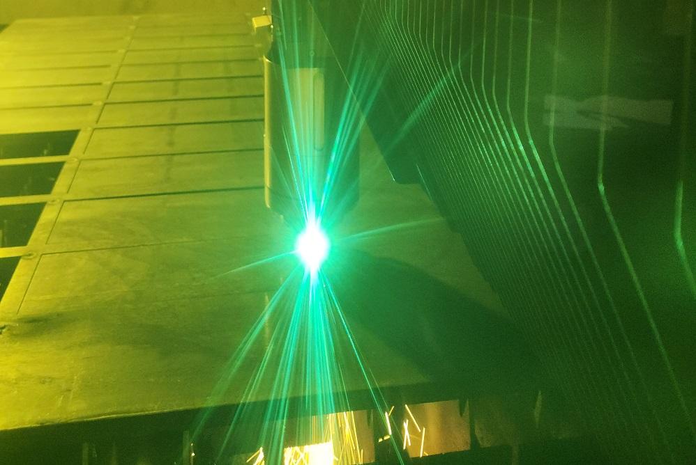
Operators test a cut program on a 30-kW fiber laser from Cutlite Penta.
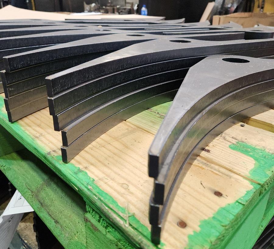
Jeff Cupples pointed to a cut edge for parts staged near a welding robot cell. The vice president of Cupples’ J&J Co. has worked for decades building the shop’s reputation as a specialist in precision plate fabrication, especially in high-powered fiber laser cutting. Those perfect edges are the result. They don’t require deburring or part leveling, and the edge taper is less than 0.005 in. The Jackson, Tenn.-based fabricator and machine shop used to have to mill that edge—but no longer. It’s now laser cut on a 30-kW fiber laser, denested, and then sent straight to robotic welding.
Cupples’ J&J got here by working closely with a variety of laser cutting machine makers (including, most recently, Cutlite Penta); assist gas vendors; and material suppliers, both the service centers and the mills. After years of experimentation, the company has come a long way.
“I’m a mechanical engineer,” Cupples said. “If I can’t break it, I know it’ll work.”
“In our experience, the fiber laser likes harder material,” Cupples said, adding that whenever a quote comes in the door requesting A36, he immediately asks if the part design can accommodate A572 Grade 50. “We’ve [also] cut Grade 60, 65, 85, and 100. With these grades, I’ve seen a 30-kW fiber laser cut a 4.5-mm-dia. hole through 2 in., and that hole just looks amazing. You can’t do that with A36. In our experience, the fiber laser just doesn’t like it.”
High-carbon-content A36 can create issues too, leaving cut edges with hard, burned dross at the bottom that can be a bear to remove. This is where Cupples takes advantage of the mini-mill’s processing control ability. “They really can control their batches, so we can get Grade 50 with something like 6% to 8% carbon. If we get something from an integrated mill, it might have 20% carbon.”
If Cupples needs to run A36, he works with material suppliers to ensure carbon content is 0.19% or less. And for all materials, the more consistent their chemical makeup, the better they perform when cut (and formed and welded, for that matter). This includes consistency in yield and tensile strength. “When you see a smooth edge and then jagged edges, if other variables are consistent, you might have a hard spot there,” Cupples said.
Material surface condition and flatness are just as critical. Cupples pointed to a stack of 5/8-in.-thick plates cut to precision—all perfectly flat. The steel was stretcher-leveled, a process that stretches the material grains and balances the material stress. That benefits high-powered fiber laser cutting in two primary ways. First, the plate flatness allows for a consistent standoff between the laser nozzle and the material surface. Second, even long plates tend to stay flat within the cut skeleton—no need for postprocess leveling, no worry of cut parts bowing up and crashing the cutting head.
The more consistent that standoff distance between the material surface and nozzle is, the better, and that can’t happen without a clean surface finish—which can be an issue. The operation sometimes works with hot-rolled pickled and oiled rolled plate, which generally has a clean surface, but when working with regular hot-rolled, the operation has been testing different methods to create a consistent, clean surface for the laser to work with. Operators often program the laser to do an etching routine that outlines the entire nest, utilizing a “swirl pierce” action that basically sweeps away the surface impurities. This, in effect, “clears a path” for the laser cut.
Of course, it would be ideal to avoid having to run that etch sequence in the first place. To that end, operators have tried blasted material as well as some (very thick) pickled and oiled plate, now available from some service centers in coil form up to 1 in. The fabricator is also just starting to experiment with laser cleaning technology that could prepare plate surfaces for optimal cutting consistency.
High-powered fiber laser cutting is an extraordinarily sensitive process. The extreme heat at the cutting lens requires an ultraclean cutting head. Even the tiniest particle of contamination can cause heat to build uncontrollably until … boom, goodbye cutting head.
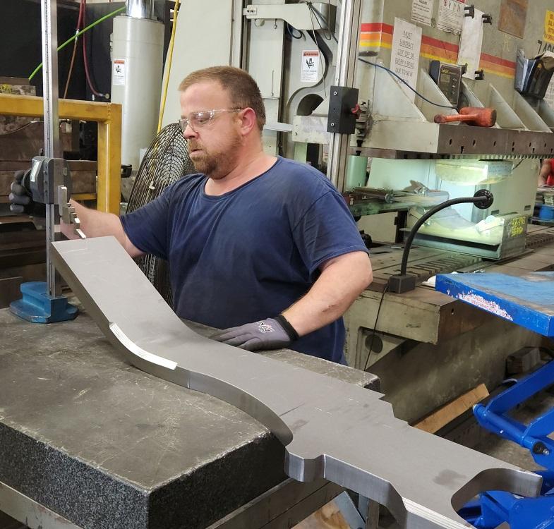
An operator measures a thick plate that he formed on the adjacent press brake—with wide-radius tooling machined in-house. This plate was plasma cut and then finish-machined and beveled on a mill. Cupples hopes to shift this part to the soon-to-be-delivered 40-kW fiber laser with bevel cutting, eliminating the need for secondary machining.
Cupples has seen a common development pattern: Cutting head technology advances (including better lens material), beam diameters widen (to cut through thick material), and nitrogen-oxygen gas mixing technology evolves, with nitrogen providing the clean cut and oxygen giving that exothermic “boost” to clear molten material from the bottom of the cut, eliminating dross. Some of the company’s high-powered machines often use assist gas mixes with 2% to 3% oxygen, while its 30-kW systems use as much as 5% oxygen.
“Tankless mixing works best for us,” Cupples said, pointing to the nitrogen and oxygen lines flowing into the Cutlite Penta 30-kW fiber laser, where the mixing occurs inside the machine, creating an evenly dispersed distribution of oxygen molecules with the nitrogen gas flow. Cupples then pointed to the adjacent oxygen dewar—a setup that produces more consistent pressure and flow than a bulk system. He then walked toward two 12-kW Eagle lasers and pointed up to a 6-in.-dia. looping pipe, connected to the 2-in.-dia. pipe that loops around the shop. “This whole arrangement acts like a surge tank,” he said, giving the entire nitrogen distribution system some reserve should multiple lasers be drawing from it at once.
The 2-in.-dia. looping pipe holds enough nitrogen to emulate a surge tank of a certain size, but when Cupples installed those two high-powered Eagles close together, gas pressure dropped when both cut simultaneously—hence the reason for that 6-in.-dia. pipe loop. Adding that effectively made the “surge tank” larger and provided more reserve for his nitrogen-hungry lasers. (The fabricator has looked into nitrogen generation, but as Cupples explained, his plant layout and sheer number of fiber lasers just don’t make nitrogen generation practical.)
Beam focus depends on the material grade and thickness. In some setups, the controller might set the focus near or just below the material surface, especially when plate cutting with oxygen or a nitrogen-oxygen mix—again, with the oxygen giving that exothermic-reaction “boost” down to the very bottom of the kerf.
Of all the parameters Cupples’ J&J laser operators tweak, gas flow is perhaps the most critical. Consistent pressure and flow must be maintained from the plumbing, through the machine and gas mixer, into the cutting head, and through the nozzle.
Cutting a smooth edge in thick plate demands a laminar flow through the kerf, and that demands a nozzle with a wider orifice. “If your nozzle orifice is too small, your gas will exit at high pressure, and that can give you turbulence,” Cupples said, adding that turbulence is the enemy of a clean cut. (In fact, when Cupples invested in his first 12-kW laser, the fabricator machined its own nozzle with a wider orifice, a design that has since been emulated and improved upon.)
“If you don’t have good gas flow, the process eventually will choke itself off,” Cupples explained. “We’ve tested the lasers several hours, running them in a zigzag pattern up and down a sheet, with the head not leaving the material. We’ve done this for a few hours, testing different thicknesses. If it cuts great and then, all of a sudden, the cut goes bad, you have a gas flow problem. We also monitor the temperature in the cutting head, to ensure it doesn’t overheat.”
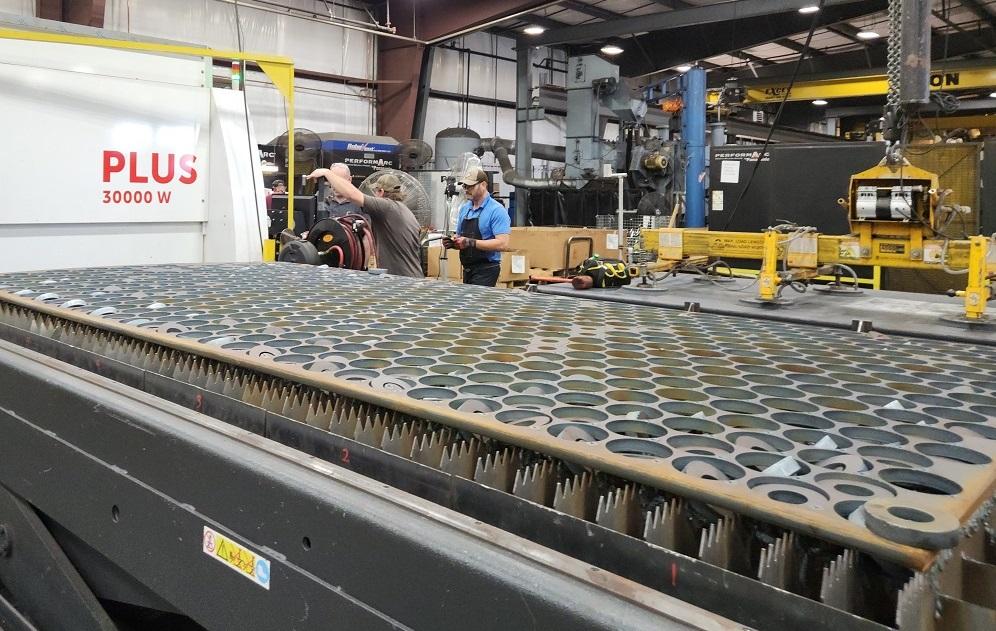
Cupples pointed to one high-powered fiber laser in his shop that had traditional drawers holding the chips and slag left from the kerf cut above. There’s no chip conveyor—and there’s a good reason for that. “As we’ve gotten to larger beam diameters to cut through thick plate, we need more laser power to keep power density,” Cupples said. “But where does it stop? We’ve had instances where we cut right through the conveyor below the slats.”
He then pointed to the bellows, which the shop works to keep clean, as well as slats and other areas of the work envelope. In fact, contamination in the work envelope can wreak havoc on modern linear drives, especially those with optical scales that enable extraordinary accelerations. Fast acceleration can make a real difference, especially in thinner plate. Magnetic scales seem to be less sensitive to contamination, Cupples said, but they offer less (though still very good) acceleration than their optical counterparts.
During my visit in August, a representative from Cutlite Penta was on the shop floor, peering closely at a test plate. He had just installed upgraded electronics in the head. He’ll also be working to install Cupples’ first 40-kW system with bevel cutting capability.
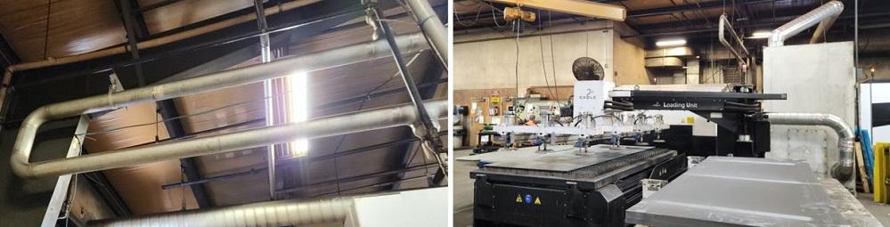
A 6-in.-dia. pipe (shown above the laser and on the left) acts as a kind of “surge tank” for nitrogen, providing enough reserve for two 12-kW Eagle fiber lasers to draw from simultaneously while maintaining a consistent gas flow.
Cupples’ J&J Co. remains one of the earliest of the industry’s early adopters. It’s central to its business model, which—judging by the shop’s growth over the past decade—is proving to be a success. In 2022, the 345-employee operation pulled in $91 million in sales. Compare that to 2017, when revenue was $46 million with 330 employees.
The company’s quest for differentiation continues unabated. For Cupples, the time spent crashing cutting heads, experimenting, tweaking, and working closely with machine vendors has been time very well spent.


The Fabricator is North America's leading magazine for the metal forming and fabricating industry. The magazine delivers the news, technical articles, and case histories that enable fabricators to do their jobs more efficiently. The Fabricator has served the industry since 1970.
start your free subscription
Easily access valuable industry resources now with full access to the digital edition of The Fabricator.

Easily access valuable industry resources now with full access to the digital edition of The Welder.

Easily access valuable industry resources now with full access to the digital edition of The Tube and Pipe Journal.

Easily access valuable industry resources now with full access to the digital edition of The Fabricator en Español.
In this episode of The Fabricator Podcast, Caleb Chamberlain, co-founder and CEO of OSH Cut, discusses his company’s...


