


Contributing Writer
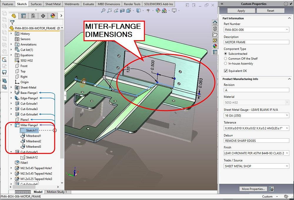
FIGURE 1A. This model of a sheet metal bracket uses a miter-flange feature to represent a jog bend. The simple sketch is used to create the bend radii and sheet metal thickness.
When it comes to 3D modeling, a CAD jockey usually has more than one way to solve a design puzzle in CAD.
For example, the creation of a virtual sharp point located at the intersection of two lines is easy if you know how. In another example, bend lines on a sheet metal drawing can be addressed with a bit of manual intervention.
Figure 1A presents a sheet metal bracket as it is being edited/reviewed in mainstream 3D CAD. A miter-flange feature (commonly referred to as a 45-degree jog bend) is selected for review, and its dimensioned three-line sketch is (barely) visible in this isometric view.
The CAD sheet metal software converts the simple 2D sketch into a perfect 3D representation of a jogged bend. The miter-flange feature results in easy editing control over angles, inside bend radii, thickness, and dimensions.
Perfect isn’t the same as realistic, but it is suitable and desirable for flat layouts and fabrication planning. 3D CAD does not (easily) model the tooling mars or dents from tooling pressure, but it does model jog bends that resemble reality and are easy to CAD-edit.
Figure 1B shows part of a 2D drawing—a section view of our sheet metal part. Of note here is the dimension Z 0.818, running along the hypotenuse of the angled bend. The Z dimension in this section view is spanning between the outside virtual sharps of the jog bend.
Sheet metal mechanics are likely to be impressed with outside virtual sharps. The rest of the world likely wonders how to physically inspect dimensions between imaginary points. These are not to be measured, however. The Z may instead be used for a particular method of flat layout calculation.
This method of using intersections (imaginary points) sometimes appears on an in-house shop/tooling drawing. Included in Figure 1B is a CAD tip about how to create the virtual sharps:
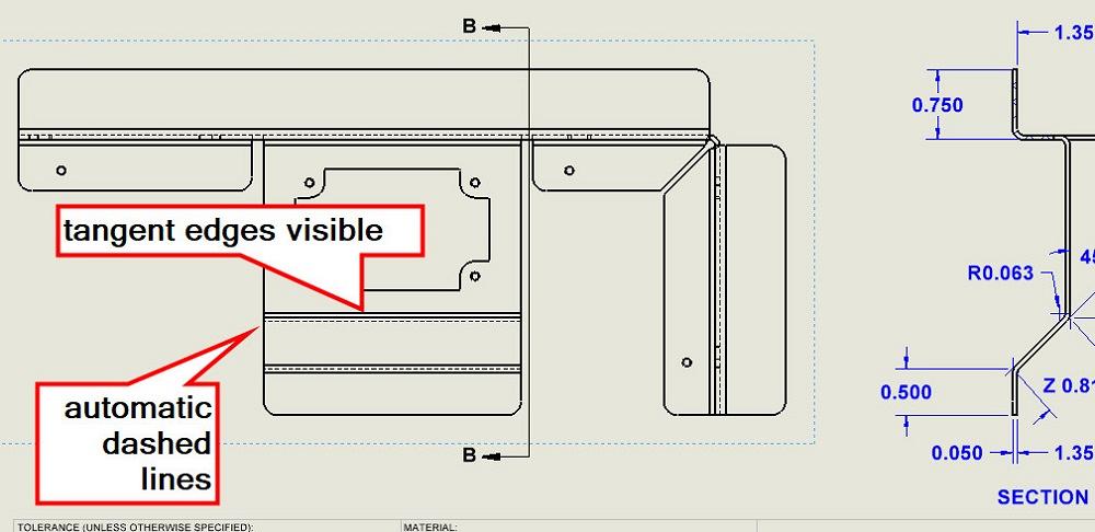
Figure 2A brings attention to the source of Section B-B shown in Figure 1B—a projected view of the entire part. We note that this projected view has both solid lines and dashed lines to represent features of the sheet metal part.
In the sheet metal trade, a dashed line means you are looking at the outside of the bend, and a solid line means you are seeing the inside of the bend. The CAD software complies with these drafting rules and adds dashed or solid lines accordingly.
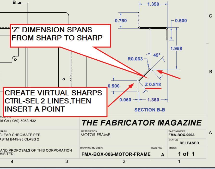
FIGURE 1B. The 2D drawing of the 3D bracket includes a section view that shows the dimensions needed for flat layout calculations. This includes the Z dimension along the 45-degree jog. To create the virtual sharps, CTRL-select intersecting lines, and then click to insert a sketch point.
The CAD software presents the model according to preferences set for the view (such as shaded and wireframe). Two view-preferences affect meaningful dashed lines; Hidden Lines Visible must be selected, and the same for Tangent Edges Removed.
That pair of settings results in automatic bend line generation that complies with drafting standards for 90-degree bends. In other words, those settings properly indicate bend direction.
For bend angles other than 90 degrees, the automatic production of bend lines is somewhat over-helpful, sometimes absent. We note in Figure 2A that, even though the 90-degree bend lines are perfect, the bend lines for the jog bend are invisible. Missing lines are missing compliance with drafting standards.
Figure 2B is an effort to correct the missing line problem from Figure 2A. The view preference for tangent edges has been changed from removed to visible. Now the software is willing to show dashed lines, along with the solid lines not only for bend edges but also for tangent edges. The software feels that the visible tangent edges are necessary to properly interpret the meaning of the dashed bend lines.
With tangent edges visible as extra solid lines, the 90-degree bends are shown with extra solid lines, so we need to understand their meaning (tangent edge, not model edge) in the drawing.
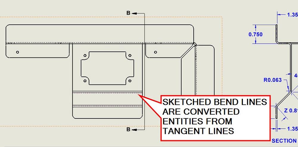
A workaround is to eschew tangent edges and instead use brute force to sketch ideal bend lines for nonperpendicular bends. This brute force is made less brutish by using the Convert Entities tool in combination with automatically generated line entities to sketch without sketching, as it were.
Just make copies of the automatically displayed bend lines (when tangent edges are visible). Such sketched entities will remain visible when the automatic tangent edges are not visible. A brutish result is seen in Figure 2C.
In Figure 2C, the 90-degree automatic bend lines comply with drafting standards, as do the sketched lines for the angled bends. Because our sketched lines are clones of the autogenerated lines, if the bend angle changes, our sketched lines automatically update to maintain proper projection in the drawing’s view.
Here’s a related CAD tip: Layers control how lines are displayed. For examples used in this column, we created and used layers in the drawing. Here’s what was done:
Here’s one more CAD tip: To change converted (sketched clone) bend lines from solid lines to dashed lines, CTRL-select all solid miscreants and put them in a layer that displays them as dashed.
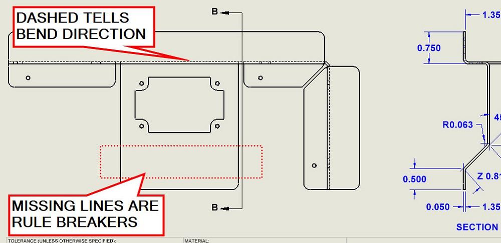
FIGURE 2A. Bend lines tell a story. Dashed lines say you’re looking at the outside of a bend. Solid line says you’re looking at the inside of a bend. The default view settings work for 90-degree bends, but not for other angles; they come up as missing lines.
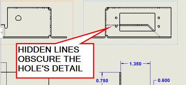
In Figure 3A, a slightly different drafting puzzle is presented. This projected view of the part presents the face with a rectangular cutout along with four related holes. The hidden lines are correct, but cluttering.
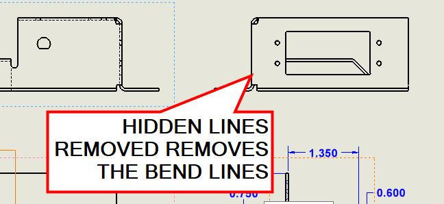
In Figure 3B, the preference to hide hidden lines is turned on. That reduces the clutter, but also hides the 90-degree dashed bend lines.
Figure 3C shows the result of cloning the dashed lines and stuffing those clones in the HID layer. Then the hidden lines can be made invisible while the sketched lines remain on display. The view is less cluttered, ready for further detailing.


The Fabricator is North America's leading magazine for the metal forming and fabricating industry. The magazine delivers the news, technical articles, and case histories that enable fabricators to do their jobs more efficiently. The Fabricator has served the industry since 1970.
start your free subscription
Easily access valuable industry resources now with full access to the digital edition of The Fabricator.

Easily access valuable industry resources now with full access to the digital edition of The Welder.

Easily access valuable industry resources now with full access to the digital edition of The Tube and Pipe Journal.

Easily access valuable industry resources now with full access to the digital edition of The Fabricator en Español.
In this episode of The Fabricator Podcast, Caleb Chamberlain, co-founder and CEO of OSH Cut, discusses his company’s...


