


Contributing Writer
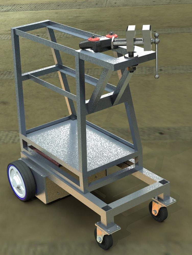
FIGURE 1. This rendered image conveys a sense of what it might be like to see the cart on a shop floor.
We are in the midst of using our lovely Custom Properties form to add information to the model preparation of the CAD project for scrutiny by others. As part of this effort, we are using a self-propelled shop cart to carry forward the discussion.
At this stage, the 3D CAD is in its middle stage of development. Many details are emerging. The progress needs to be reviewed and priorities set for the next round of activity.
The audience participating in the model review includes peer CAD personnel, manufacturing, purchasing, quality control, inventors, investors, compliance committees, marketing, and customer support.
Figure 1 is an example of a rendered image created to mimic what the real-world product will look like. Lighting, scenery, and textures all contribute to the realism, or lack thereof, in the image.
The previous episode of this column (and all if its disclaimers about the cart not being real or for sale) discusses the benefits and boundaries of unrealism in presentation.
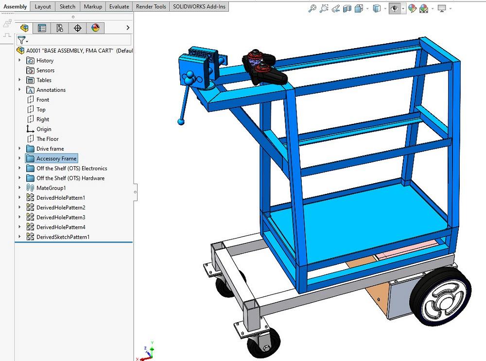
Figure 2 is a screenshot of a CAD workstation with the cart project underway. This is how a collaborator might see the project. There are three functional sections: the graphics window in the middle, the Feature Manager to the left, and a detail panel to the right. When Figure 2 was created, the workstation was being used to render Figure 1. The preview of the rendering setup is visible in the graphics window.
Because we want to dazzle our peers, the clutter in the list displayed by the Feature Manager needs improvement. It is basically a run-on sentence. Fortunately, the CAD system allows the creation of folders to organize the Feature Manager.
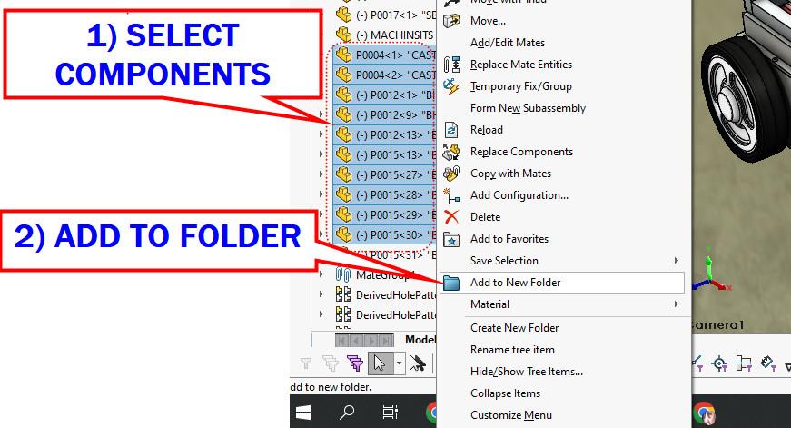
Figure 3 shows a two-step process for setting up a folder with components:
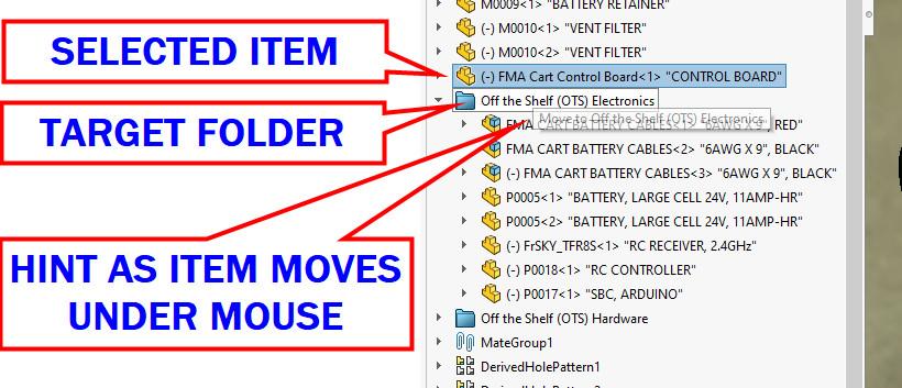
If a folder already exists, items can be dragged into or out of it. Figure 4 captures the process of dragging the component FMA Car Control Board into the folder named Off the Shelf (OTS) Electronics.
Figure 5 shows a working set of folders in the Feature Manager for this cart project. The folders have been named Drive Frame, Accessory Frame, Off the Shelf (OTS) Electronics, and Off the Shelf (OTS) Hardware. Compared to the Feature Manager shown in Figure 2, this is much tidier.
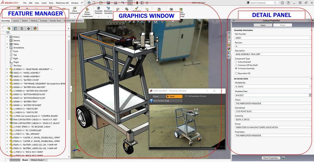
FIGURE 2. The CAD workstation might be used to review the project. We have designed a lovely Custom Properties form (right), and the 3D model (graphics window in the middle) is beautiful. The Feature Manager is a long list that must be scrolled to review. It is a random list. Functionally for review, it is a run-on sentence.
Perhaps for a wider audience of review, Exploded Views can be used in highlighting components and their relationship to the overall assembly. An Exploded View could show how someone can gain access for service of an item.
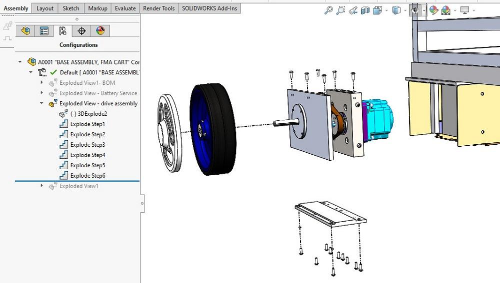
Figure 6 lists the four Exploded Views created so far are listed. The Exploded View of the drive assembly has been activated, and the resulting disassembly of one of the drive assemblies is evident.
Here’s a CAD Tip: The Exploded View can be animated. The sequence of steps can be re-ordered after it is created to make a more realistic assembly/disassembly movie.
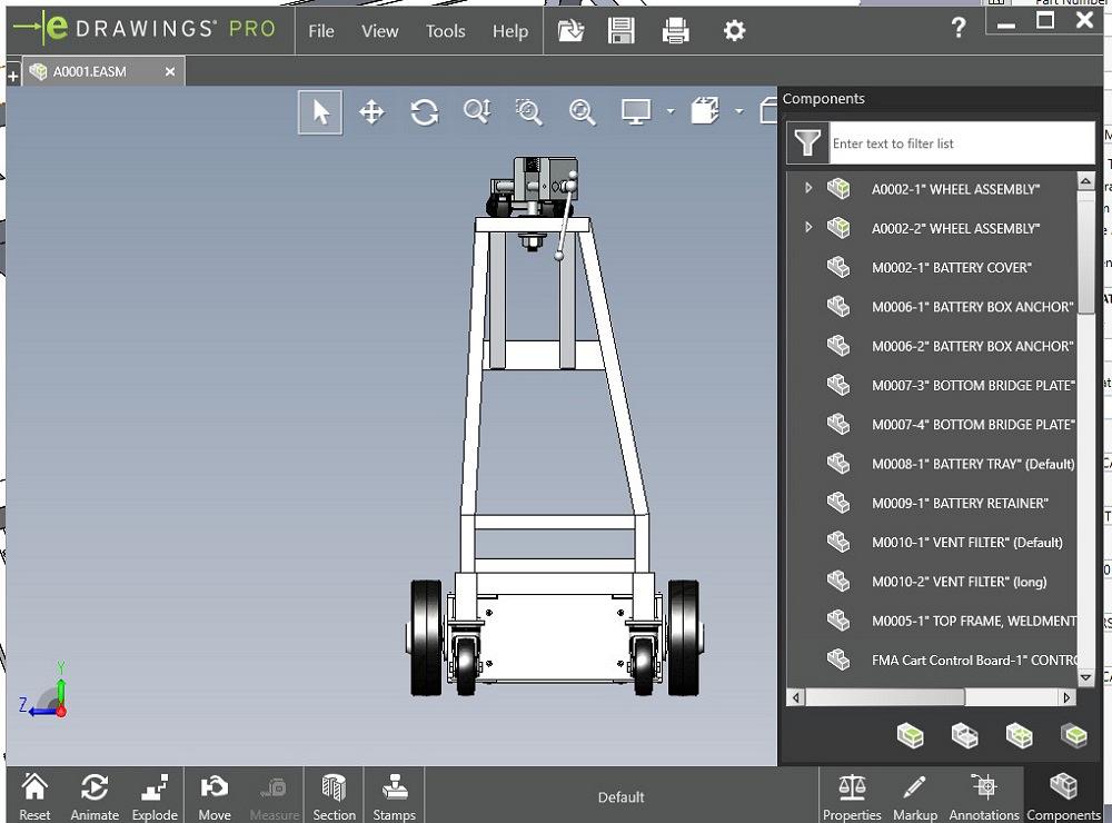
The use of 3D viewers is a useful means of review. eDrawings (see Figure 7) provides access to component detail, animations, and other views. Its user interface is reasonably intuitive, even for the non-CAD expert. Note that much of the work that went into Figure 1 (textures and colors) can be used by the 3D viewer (eDrawings, Solidworks Viewer).


The Fabricator is North America's leading magazine for the metal forming and fabricating industry. The magazine delivers the news, technical articles, and case histories that enable fabricators to do their jobs more efficiently. The Fabricator has served the industry since 1970.
start your free subscription
Easily access valuable industry resources now with full access to the digital edition of The Fabricator.

Easily access valuable industry resources now with full access to the digital edition of The Welder.

Easily access valuable industry resources now with full access to the digital edition of The Tube and Pipe Journal.

Easily access valuable industry resources now with full access to the digital edition of The Fabricator en Español.
In this episode of The Fabricator Podcast, Caleb Chamberlain, co-founder and CEO of OSH Cut, discusses his company’s...


