


Contributing Writer
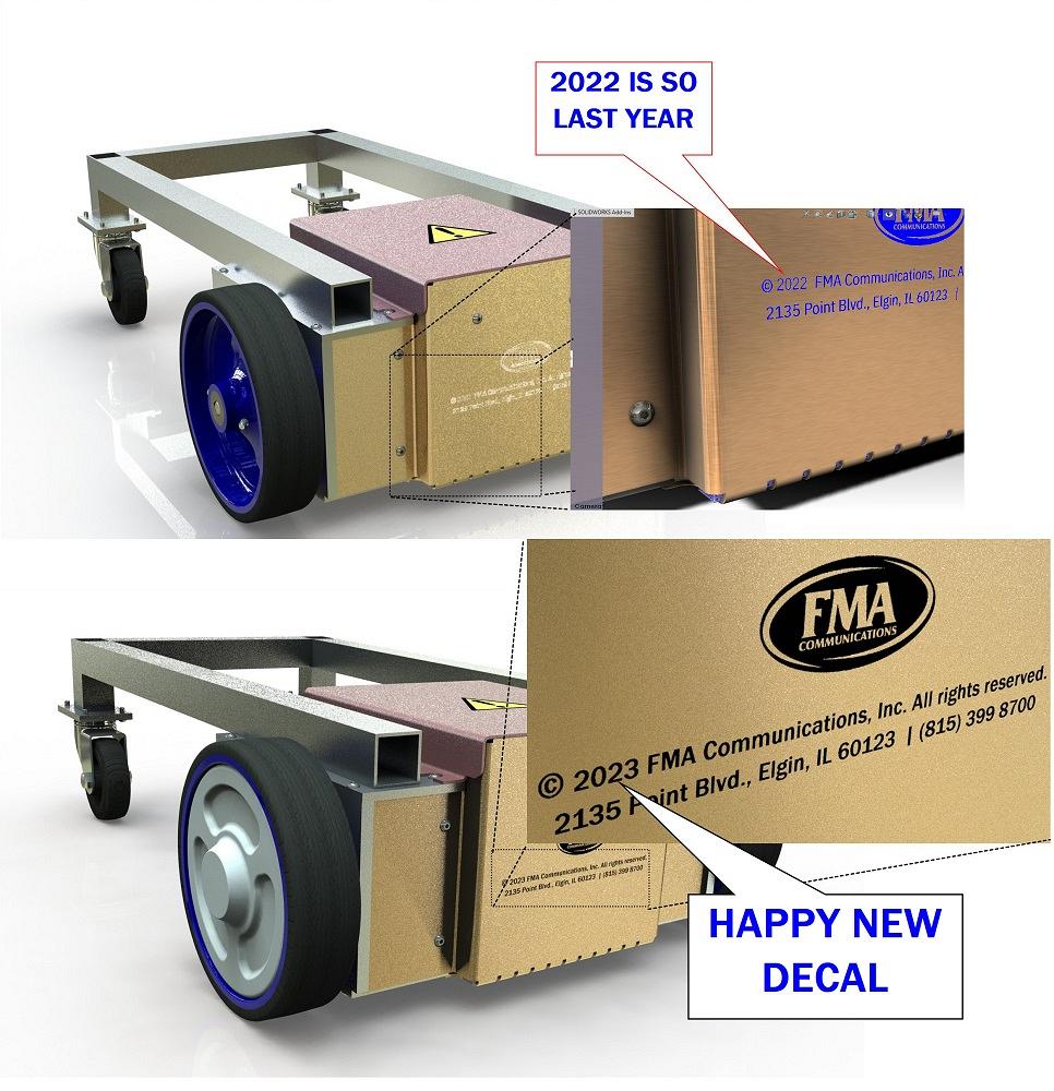
FIGURE 1. The upper image shows the decal from 2022. The lower image contrasts that with the improved decal for 2023. Higher-resolution source image files allow for the creation of more realistic decals in the CAD model.
Happy New Year! With that said, the upper image in Figure 1 shows an annual change that is needed to the decal being used in an imaginary shop cart project. The overall view of the cart shows the decal’s location, and the close-up (to the right) shows the “©2022” that should now be “©2023.”
With the brand of CAD being used here, decal has special meaning. It is a CAD feature—an image applied to one or more surfaces of a CAD model.
Disclaimer: The FMA logo and image used in these illustrations are derivations from the FMA website. The illustrations in this article are approximate and are not to be confused with actual trademarks and registrations of FMA.
The parent of the 2022 decal JPG file is an edit of a 2021 decal JPG. Just the year has been layered over with new text. During one of those annual edits, an accidental drop in resolution from 1,200 to 300 DPI became something to live with. Several ghostly dots surround the logo. These are little harpies that keep the author humble.
As a CAD technique, this FMA logo decal uses a mask file to hide the unused portions of the JPG image file. As an alternative to creating a mask file with inverted colors, the CAD system can use the image file to create a mask by inverting it for you. One can even mask on a color-by-color basis. Regardless of technique, when the mask is working well, the rendered result resembles reality—an actual screen printing on sheet metal, for example.
Sadly, the 2022 mask file has artifacts. These artifacts result in something that is unrealistic when viewed at close magnification. The resulting decal was barely suitable for making illustrations, but not adequate for fabrication.
Returning to Figure 1, the white-looking lettering is the result of low resolution expanded beyond useful scale. The mask is overwriting the image. When an image with proper resolution is used to prepare the decal, the color and text become recognizable, as may be noticed in the zoomed-in view.
The lower image in Figure 1 is improved for 2023. Higher resolution (way more pixels) in the “2023 JPG file” allows creating a decal that can be stretched to size without too much loss of fidelity. Here’s a tip for creating image files for use as decals: Shrinking is usually easy, and stretching is the challenge.
Here’s another CAD tip for better stretching, as it were: PNG offers more versatile fidelity than JPG when it comes to adjusting the decal to fit the model. Otherwise, use as many DPIs as may be tolerable in the JPG files. But there is a penalty for fidelity: Resolution slows down the graphics system and increases file size.
As a demonstration of bad behavior, where the decal is hacked together instead of being derived from high-resolution files received from the graphics art department, this CAD jockey used photo-editing software to resize the logo screenshot captured from a website. The screenshot was pixel-replicated to expand it from roughly 0.5 in. to about 3 in.
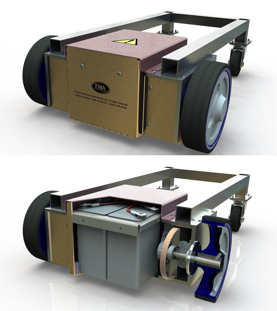
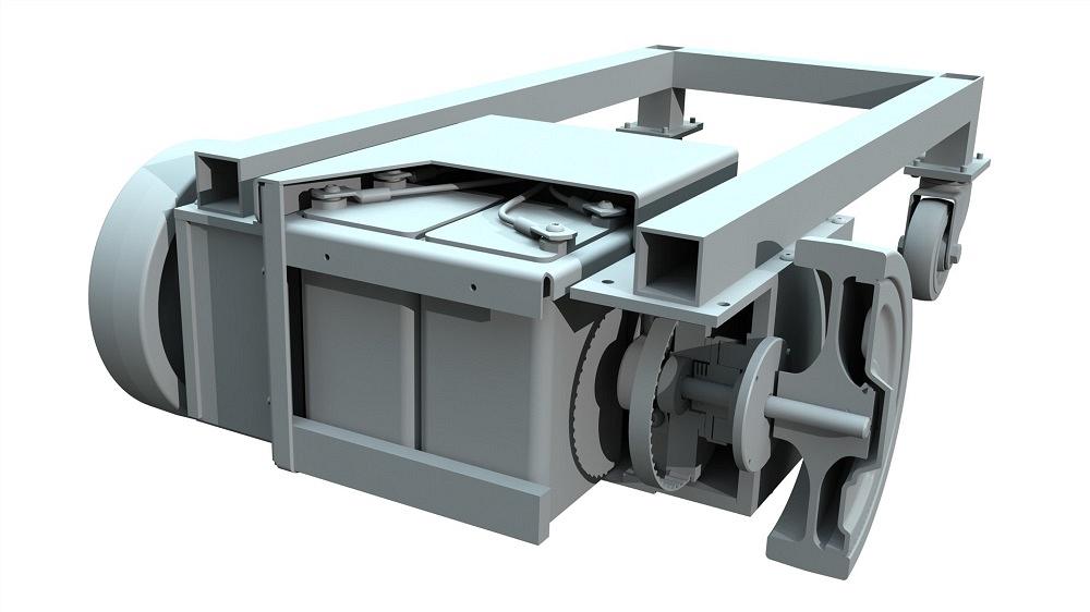
FIGURE 2. The upper image reveals that the FMA logo decal for 2023 has rendered nicely. The environmental reflection looks good from all angles. The lower image is using a zonal section cut to reveal the components of the drive train assembly. When this pair of images are viewed in sequence (in a PowerPoint, perhaps), it creates an interesting animation of before and after.
That fuzzy image of the FMA logo was then converted to black and white in anticipation that fewer colors (two) make it easier for the masking to work as desired. The remaining odd dots and zaggy edges around the captured FMA logo were then erased to leave a sharper (albeit unapproved) perimeter.
With the FMA logo resembling goodness, the annual text was added and scaled to match the scale of the FMA logo for this cart project. That JPG file is inverted and used as a mask to create the decal. The upper image in Figure 2 shows the result—a very crisp image even when viewed closely.
Presentation of the design with realistic decals and textures often leads to improvements in the design, even before the presentation is completed. Seeing the model for others makes it possible to find the overlooked.
Section views that include or exclude components, in addition to textures and shadows, for instance, help to reveal gaps and omissions in the design.
The images in Figure 2 were created for use in future discussion of the fit and function of parts in the drive train. The lower image in Figure 2 uses a zonal section view.
Zonal means more than one section plane in use. In this example, the front and right planes are being used. The right plane has been rotated at a slight angle to reveal more of the left-hand battery.
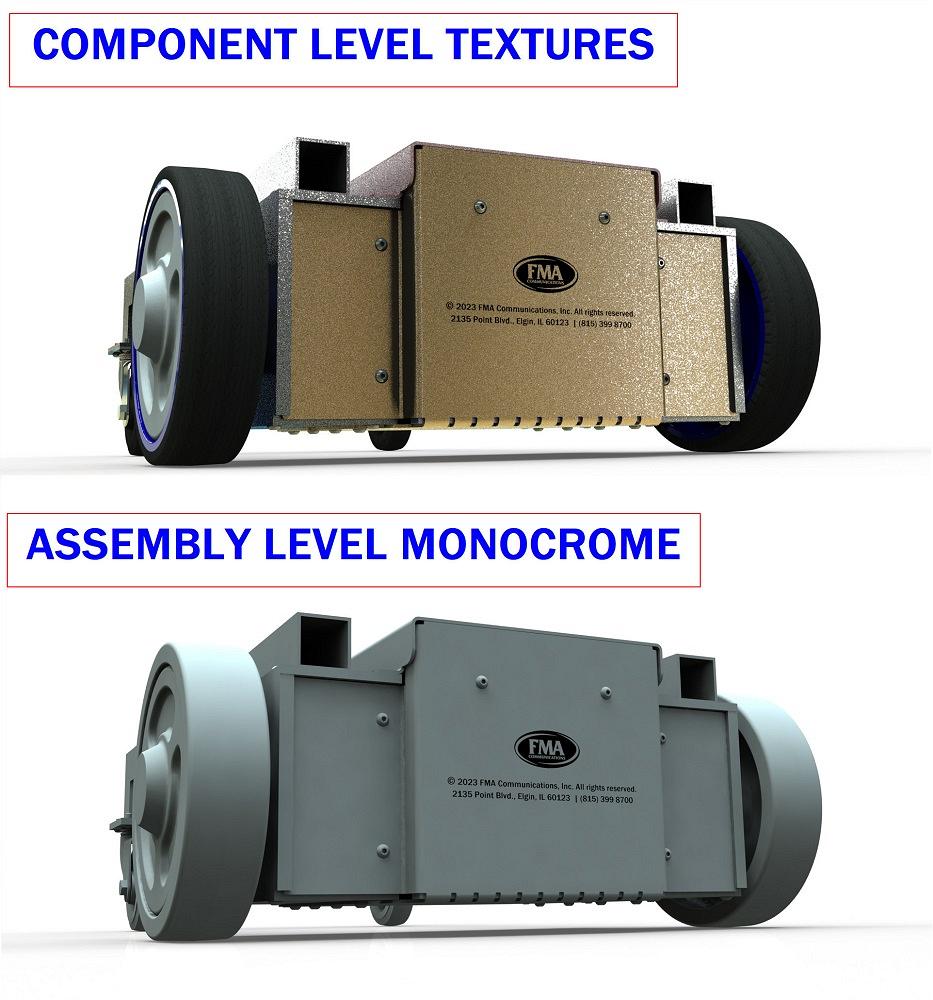
As a side note, Figure 3 explores a method of presenting a product for review. The upper image uses the colors and textures from the components in the assembly. One may distinguish rubber tires from chromated aluminum, for instance.
As an alternative presentation, the lower image in Figure 3 reveals a solid color that has been applied to the entire assembly. The thought is to use tools to emphasize shape versus texture.
Maybe these aren’t the side notes, and the rest of the article is a side note. Figure 4 is using a zonal section view and monochrome palette to present the “bones” of the cart in a self-guided tour. Perhaps this will be used in a discussion of the use of a tolerancing schema to apply the function and relationship between components in an assembly to the drafting of the dimensions and tolerances on their drawings. We’ll be referencing faithful reader Mike Matusky’s thoughts on geometric dimensioning and tolerancing along the way.


The Fabricator is North America's leading magazine for the metal forming and fabricating industry. The magazine delivers the news, technical articles, and case histories that enable fabricators to do their jobs more efficiently. The Fabricator has served the industry since 1970.
start your free subscription
Easily access valuable industry resources now with full access to the digital edition of The Fabricator.

Easily access valuable industry resources now with full access to the digital edition of The Welder.

Easily access valuable industry resources now with full access to the digital edition of The Tube and Pipe Journal.

Easily access valuable industry resources now with full access to the digital edition of The Fabricator en Español.
In this episode of The Fabricator Podcast, Caleb Chamberlain, co-founder and CEO of OSH Cut, discusses his company’s...


