


Contributing Writer

CAD guru Gerald Davis troubleshoots a CAD drawing with key omissions and spelling errors as reminder why debugging and proofreading is important. Getty Images
The pop quiz shown in Figure 1A—also known as a drawing under review—has several errors and omissions. Such petty agonies burn time. Oh, that they could be avoided. Some answers to the quiz are shown in Figure 1B.
The task at hand is to tidy up (synchronize) this drawing’s expectations with what product manufacturing information (PMI) is available in the 3D database. To provide context for this story of layered detail, we are participating in a scenario where drawing sheet formats and CAD models are being brought into synchrony under our authority to end all blank looks.
The good news is that this title block has several entries that are filled in correctly. For example, the TOLERANCE block populated itself with PMI from the 3D model.
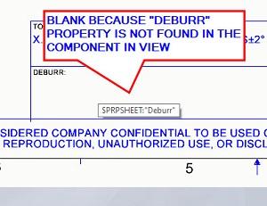
Sadly, the DEBURR block is badly behaved, as may be noted in both Figures 1A and 1B. The block’s emptiness indicates that there is a discrepancy between the PMI retained in the 3D model and the expectations of PMI to be retrieved by this 2D drawing file.
This 2D drawing file is looking for something that the component in view—the 3D model’s file—does not have. To correct the problem, we will drill down through several layers of detail. The first puzzle is to know what this example drawing desires by way of PMI.
The drawing’s title block is sheltered from accidental editing by what this brand of CAD calls a “sheet format.” The sheet format is seldom edited and is, in general, a constant, indelible border for the 2D drawing. Once it is set up, just accept its existence as friendly.
While seldom editing the sheet format—as is being demonstrated in Figure 2A—one may hover the mouse over the problem text box to reveal the name of the missing. In this example, $PRPSHEET:“Deburr” hears no reply. We propose an audio track featuring Anjelica Huston in courtly drama thundering, “The drawing accuses the assembly of not knowing how to deburr. The CAD jockey presides.”
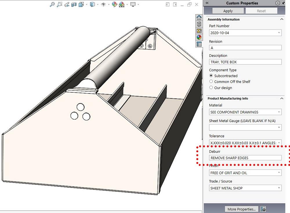
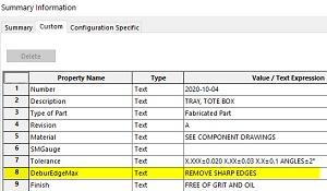
In response, our CAD jockey sees red dots on the Custom Property form shown in Figure 2B. That form, while it is presenting PMI retained by this assembly, offers deburr instructions. REMOVE SHARP EDGES is right there, as plain as can be.
This indicates that there is a discrepancy between the Custom Property form’s labeling (such as Deburr) and the name of the PMI entry being presented under the sly guise thereof. Imagine Frank Readick Jr.’s droning drawl: “Only the assembly knows what shadowed property lurks within the component in view.” Try that line on your spouse this evening! (For those who never gathered around a radio for an evening program, Readick Jr. was known for his introduction to the popular radio drama “The Shadow.”)
It’s time for a sidebar delving into some detail: File properties are a Windows feature. The CAD system uses the operating system’s file properties behavior to embed a user-definable database for PMI entries in the 3D model.
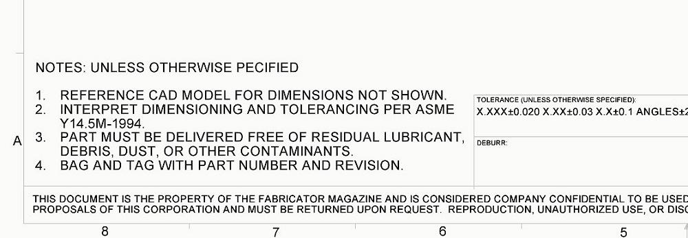
Figure 1A. A drawing under review is shown with a few of its errors and omissions. Catch them if you can.
To edit such file properties, Windows offers a table-oriented user interface (UI) (see Figure 2C), whereas the CAD system offers a form-oriented UI (shown in Figure 2B). The CAD system’s Custom Property form is a locally grown convenience for data entry. The Windows table UI is the foundation without disguise.
“This Custom Property form is accused of displaying deburr instructions under a faulty title,” Tom swiftly belabors. (If you don’t savor Tom Swift jokes, then I don’t need to apologize. Just move along.)
The Windows level of file properties shall reveal the fact of the matter. The CAD system’s File>Properties menu takes us there. The properties that this 3D model retains are presented in a Windows table format in Figure 2C.
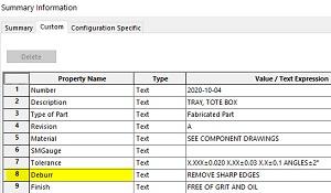
Please note what amounts to a spelling error—Deburr vs. DeburrEdgeMax. That error is correctable by double clicking in the table’s cell and entering a new value. Tada! Figure 2D shows Deburr as the property name and it has the value REMOVE SHARP EDGES.
Now we know. The root cause of the blankness on the title block was because of the assembly’s lacking information, which was due mostly to the Custom Property form. The assembly did not present Deburr as a property to the world. It offered DeburrEdgeMax instead because the Custom Property form rules everything and will create any property that it thinks should exist if it doesn’t already.
The misleading Custom Property form knows nothing of the property Deburr. It was designed (with Property Tab Builder) to show a readable heading instead of something lumpy like DeburrEdgeMax.
Pomp and circumstance from the orchestra. We have CAD jockey judgment: The Custom Property form does not match well with the drawing template and is found to be faulty!
A first step in correcting this problem is to rename the property DeburrEdgeMax to become Deburr. Renaming this property in this 3D model instantly corrects the problem with this 2D drawing’s deburr note being blank.
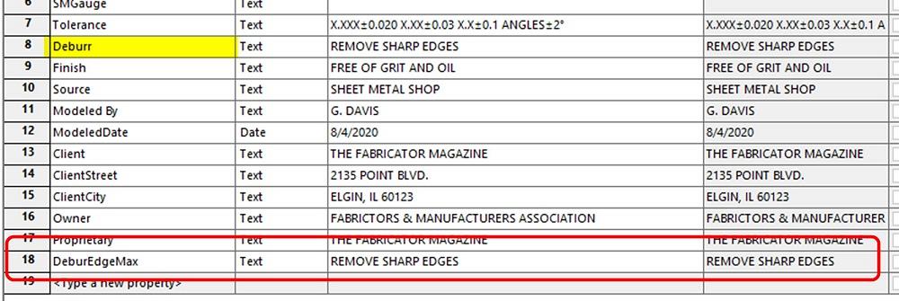
Figure 2E shows an unintended and durable consequence of the quick fix. The property named Deburr exists (yellow highlight), and that is good. The errantly named property, DeburrEdgeMax (marked in red), keeps coming back because of the behavior of the malfunctioning Custom Property form. Perhaps even more confusing, the property Deburr is not connected to the Custom Property form; it is basically an orphan property.
For this episode, permanently deleting the unwanted property DeburrEdgeMax from this assembly, as well as using Property Tab Builder to tame the Custom Properties form to adopt an orphan, was completed off-camera.
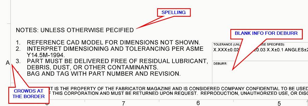
Figure 1B. The errors and omissions are detected. The specifications for DEBURR are blank. One may “pecify,” but not in mixed company. And, alas, the sheet format has some spacing and layout issues.
In retrospect, one could have edited the drawing’s sheet format so it was expecting a property named DeburrEdgeMax as opposed to the changing of the 3D model and custom form to please the 2D drawing’s request for Deburr.
You decide who’s boss when synchronizing the PMI schema. In this scenario, the 3D models and 2D drawings are being merged from various CAD efforts that bring a barely coordinated legacy of custom properties and drawing templates into the mix. Now is the time to name names to match meaning and function. Once decided, the Custom Property forms (one each for parts and assemblies) will be updated, as will be done to the sheet format and document templates. Give us this day our happy CAD system.
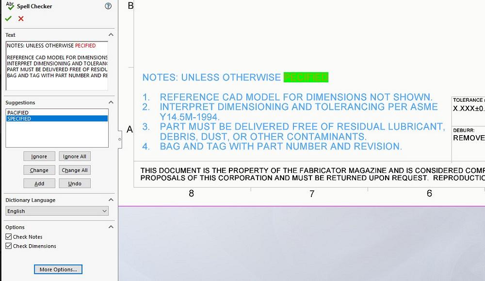
Resuming the tidy-upping effort for the drawing at hand, Spell Check (F7 on a keyboard near you) is shown catching a mistake in Figure 3. Perhaps even more wonderful than proper spelling, Design Checker will check dimensioning standards, fonts, materials, and sketches and may also be trained to cast Spell Checking as part of its scrutiny.
The remaining problem with crowding and spacing of the sheet format is a matter of editing to create and save a better sheet format. The improved sheet format that is saved from this drawing may, in turn, be applied to other drawings so they gain the same nice appearance.


The Fabricator is North America's leading magazine for the metal forming and fabricating industry. The magazine delivers the news, technical articles, and case histories that enable fabricators to do their jobs more efficiently. The Fabricator has served the industry since 1970.
start your free subscription
Easily access valuable industry resources now with full access to the digital edition of The Fabricator.

Easily access valuable industry resources now with full access to the digital edition of The Welder.

Easily access valuable industry resources now with full access to the digital edition of The Tube and Pipe Journal.

Easily access valuable industry resources now with full access to the digital edition of The Fabricator en Español.
In this episode of The Fabricator Podcast, Caleb Chamberlain, co-founder and CEO of OSH Cut, discusses his company’s...


