


Contributing Writer
Getty Images
Editor's Note: If you would like to download the 3D CAD files associated with this column, click here.
You can find 3D models that are available as STEP files for import into 3D CAD, but such giveaway models do not always provide a suitable result. Correcting the problems after import may involve removing features, adding features, splitting bodies, and adding kinematic mates in assemblies.
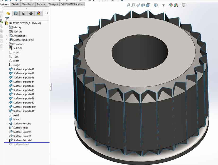
As an example, Figure 1A shows CAD for a digital servomotor that was imported with minor grief, such as some features that don’t match a part number on a website. The CAD settings for STEP import caused this import to be a collection of surfaces. With different settings, a STEP file can be imported as solid bodies, surface bodies, or as disjointed surfaces. For this demo, we are knocking cobwebs off of surfaces and surface modeling techniques.
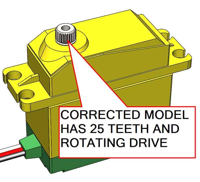
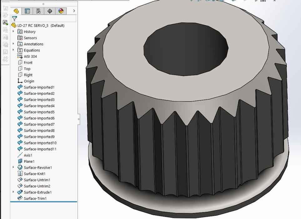
Figure 1B is a preview of what the ideal imported model would have been—a dimensionally accurate body with properly moving parts, pretty textures, and accurate mass properties.
Fortunately, the imported model is a good starting point. It will be changed to feature a 25-tooth splined drive gear with realistic kinematic behavior.
Moving from solid to surface modeling is as easy as deleting a face from a solid body. Replace the missing face and you have two surface bodies. If those surfaces completely enclose a volume, then those surface bodies can be knitted to create a solid body.
Solid modeling tools are running macros, behind the scenes, that perform surface modeling tasks. The rules for using the solid modeling tools are sometimes more cumbersome than simple surface operations. As a work flow, surface modeling can be entertaining (“It’s more efficient,” we say to the boss) when compared with conventional solid modeling.
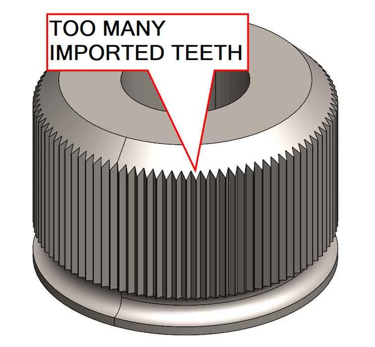
We are using the imported model shown in Figure 2 as an example of something that is mostly good, but not perfect. It has too many teeth. If this were a solid body, we could extrude a cylinder to fill in the bad teeth and then cut new teeth. But we are going to deal with imported surfaces instead.
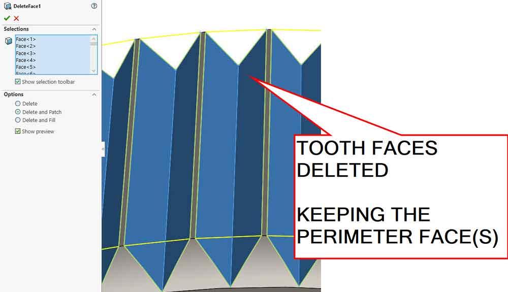
Whether the model is imported as a solid body or as surface bodies, one of many possible ways of getting rid of the bad teeth is to use the Face Delete and Patch tool, shown underway in Figure 3. The flat faces in the V cuts have been selected for deletion followed by automatic patching.
The Face Delete and Patch operation results in a billet blank ready for hobbing or splining. When automatic patching works, it feels like magic. If the imported model has too many conflicts, auto patch may not work. The radio button for Face Delete Only is a work flow alternative that includes manually closing holes and gaps using tools like Surface Untrim.
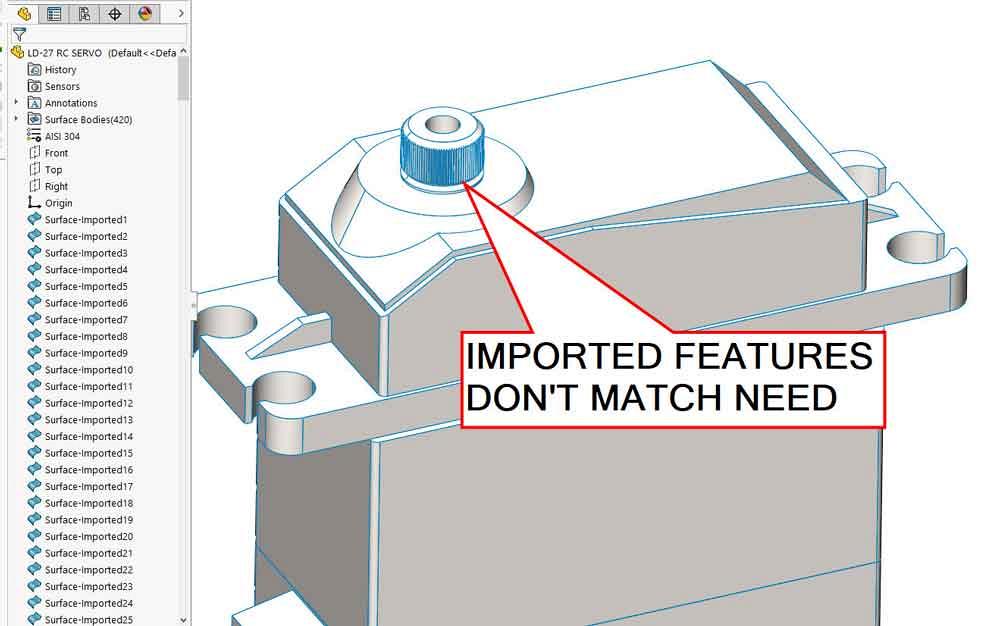
Figure 1a
The imported STEP file is mostly perfect except for the drive gear. It won’t move, and it has bad teeth.
Once the bad teeth are gone, you have various options for making new teeth. To model the ideal surfaces in a 25-tooth gear, make a sketch, extrude to create a V surface, and then pattern that V shape 25 times. The resulting surface mess is shown in Figure 4A. Surface Trim merely requires a few clicks on the unwanted faces to reveal the teeth in Figure 4B. It looks like a solid body because it is. The last Surface Trim was used to create a solid body from the surface bodies it had to work with.
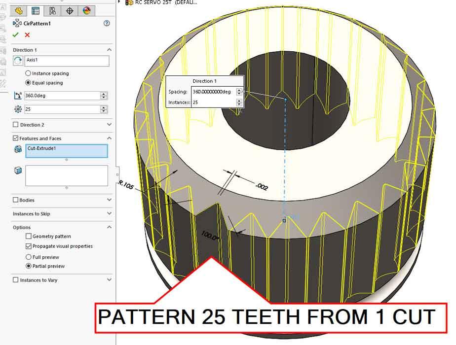
As suggested earlier, surface modeling isn’t required. In Figure 4C, the gear billet is a solid body. A circular pattern of a conventional Cut Extrude for one tooth finishes splining the gear. If the imported model is not a solid body, Surface Knit could be used as the first and only surface modeling operation to transform the imported surface body of the gear into a solid body before editing the teeth.
The process of getting an imported surface body to knit into a solid body can involve Import Diagnostics to repair faces and close gaps. Also, some combination of operations to delete unwanted elements and add the missing surfaces is needed to completely enclose a volume of space.
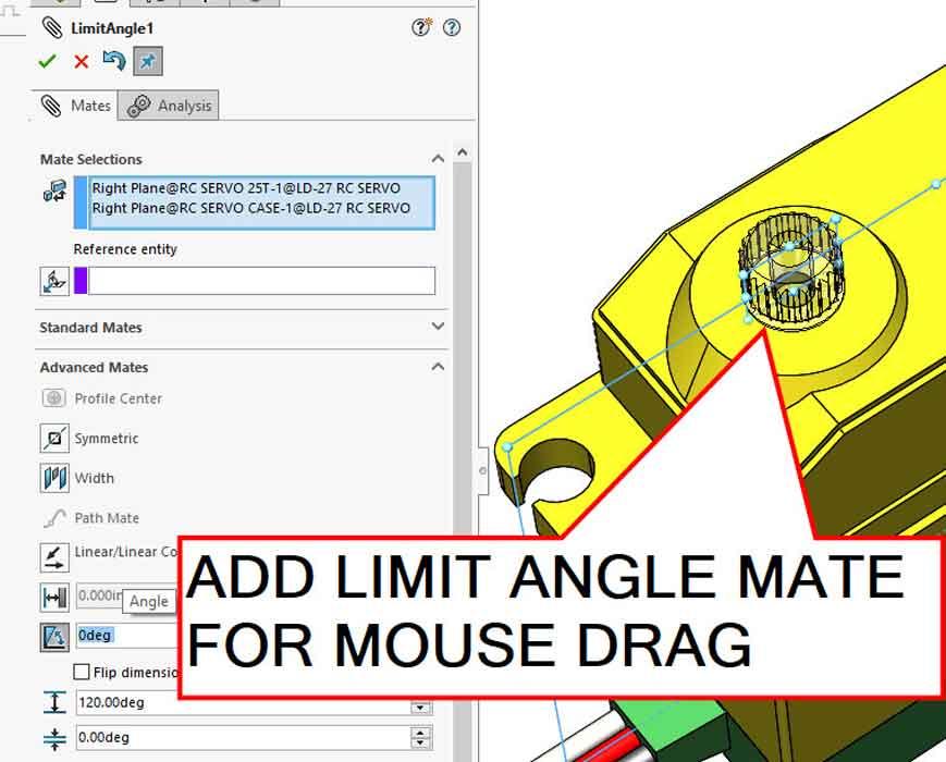
A final flourish in embellishing this model is to limit the rotation of the gear with a limit mate, shown in Figure 5. Realistic motion in a modeled mechanism can be useful for simulation and presentation of a design. In this example, the servo has a 120-degree range of motion.
Gerald would love for you to send him your comments and questions. You are not alone, and the problems you face often are shared by others. Share the grief, and perhaps we will all share in the joy of finding answers. Please send your questions and comments to dand@thefabricator.com.


The Fabricator is North America's leading magazine for the metal forming and fabricating industry. The magazine delivers the news, technical articles, and case histories that enable fabricators to do their jobs more efficiently. The Fabricator has served the industry since 1970.
start your free subscription
Easily access valuable industry resources now with full access to the digital edition of The Fabricator.

Easily access valuable industry resources now with full access to the digital edition of The Welder.

Easily access valuable industry resources now with full access to the digital edition of The Tube and Pipe Journal.

Easily access valuable industry resources now with full access to the digital edition of The Fabricator en Español.
In this episode of The Fabricator Podcast, Caleb Chamberlain, co-founder and CEO of OSH Cut, discusses his company’s...


