


Contributing Writer
Getty Images
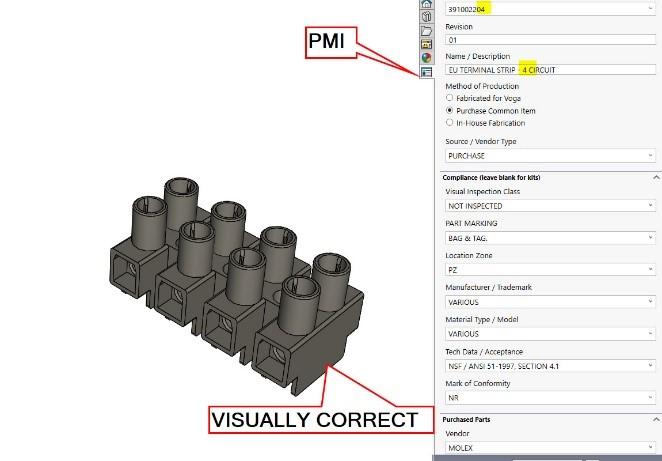
Figure 1 shows a 3D CAD model representing a terminal strip in the EU style. This model was downloaded as a STEP file, courtesy of Molex Inc.
The STEP file was imported into a brand of mainstream 3D CAD and massaged with Import Diagnostics so that textures and colors would be well-behaved.
In the author’s opinion, the most important part of the CAD task is entering the product manufacturing information (PMI). PMI includes materials, textures, default tolerance, part number, and description.
The PMI for this off-the-shelf component is displayed to the right of the model in Figure 1. We thank Voga Coffee Inc. for sharing their version of a Property Tab Builder form. Fans of this column may recall our extensive discussion of the design of Voga’s brewer. They have prospered during Lockdown 2020 and send their best to you all. It is likely that your version of a Custom Property Tab form will differ.
PMI has been a topic in several episodes of this column. May 2019 delved into the data collection aspect of PMI in some detail.
Figure 2 shows a four-circuit terminal strip that is kindred to Figure 1. The four-circuit model was created by modifying a completed copy of the eight-circuit model.
Thus, the template model for the four-circuit version started out with the eight-circuit version’s PMI. As recommended work flow for the CAD jockey, the copied PMI is then a breeze to edit—merely changing eight to four in a few places, in this example.
The four-circuit version could have been requested as a downloadable STEP, just as the eight-circuit version was, but that would have required entire duplication of the PMI task. (Insert sweaty, exhausted, put-out CAD jockey emoticon here.)
Insert>Face>Delete extends our labor-saving suggestion theme beyond PMI to include visual accuracy. Deleting a face instead of modeling over the top of it is a work flow that the author frequently uses.
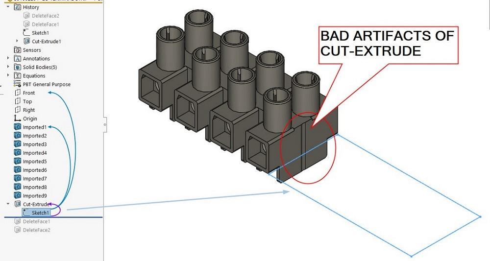
Divide and conquer. The result of the cut-extrude that cuts the eight-circuit into a four-circuit part is visible in Figure 3. It’s good that there are four circuits. It’s bad that there are also unwanted artifacts. These are circled in red on the end of the part where it was cut.
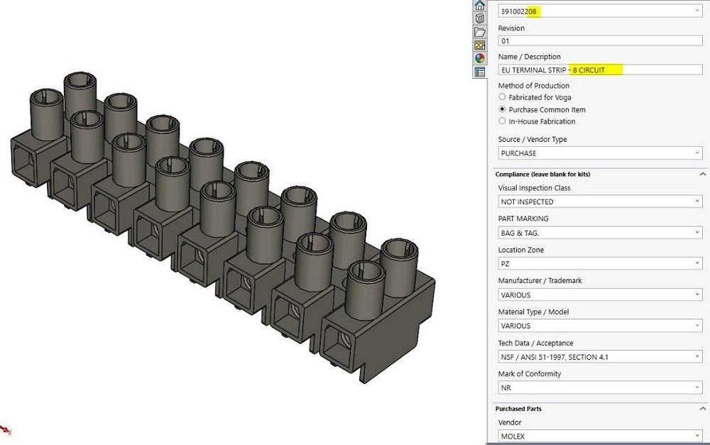
Figure 1. Molex provided a downloadable STEP file of an eight-circuit EU-style terminal block. Our required PMI for procurement has been added to the 3D model. PMI is shown to the right. Note the emphasis on the eight-circuit PMI.
Figure 3 includes the sketch of the cut-extrude that defines the four-circuit version. (Note the robin egg blue rectangle.) In this demonstration, the sketch is a simple rectangle that cuts through all bodies in both directions.
Due to wonderful diligence and disclosure on the part of Molex, the downloaded STEP file includes 3D bodies for the metal terminals as well as for the plastic barrier strip. (When the author tried to use a single-line sketch to make the divide as opposed to the rectangle shown, all eight of the wire terminals remained; only the barrier strip body would be encompassed by the scope of the cut-extrude. Rather than add a feature to delete those four bodies, the sketch was changed from sketch to rectangle to enclose all of the nuisance.)
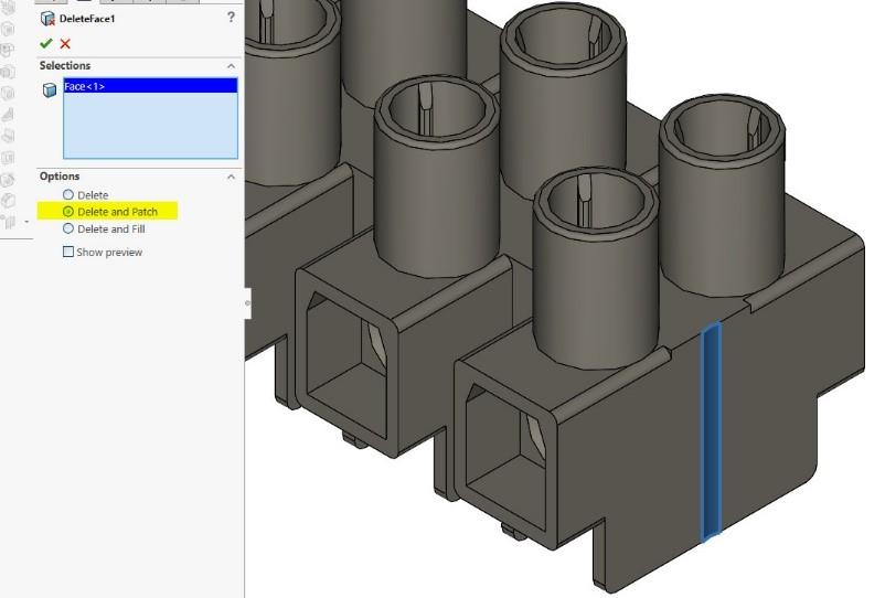
To improve the appearance of the four-circuit model, we shall delete unwanted faces in two steps. Figure 4 shows the properties of the first of the two corrective measures that will be required.
The unwanted nick in the surface—noted with cyan highlight—is the result of cutting through a mounting hole in the eight-circuit model. If we were to literally saw an eight-circuit item, the result would be very much like this model.
Insert>Face>Delete is a recommended modeling technique because it has very low impact on CPU resources. No underlying sketch or reference surface features have to be resolved, especially when compared to the use of a boss-extrude or sweep.
The Parasolid kernel is directly involved in most of the work that Insert>Face>Delete invokes. It’s a low-overhead CAD feature. Our models are, after all, merely math equations disguised as lists. Keep the list short and the steps sweet. Only CAD jockeys savor such folly. It is our wont.
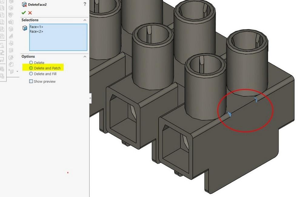
In Figure 5 we see progress towards a visually appealing model, yet we also see an interruption to the smooth fillet along the edge of the part. To remedy this, we select the faces at the ends of the sharp segment for deletion.
In both Figures 4 and 5, the radio option button for Delete and Patch is selected. The other radio button options are useful but not fully described in this article. The Delete option will transform a solid model into a surface model. The Delete and Fill option deals with contours better than mere patching does.
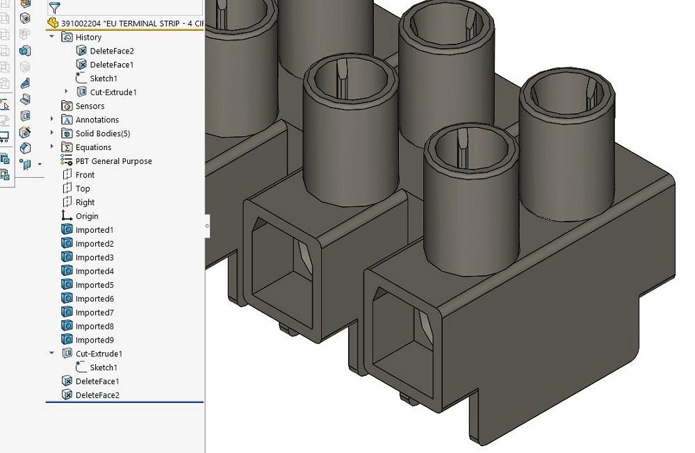
The remedial result is shown in Figure 6. Insert>Face>Delete is the menu path to such glory. Upon reflection, we could omit the cut-extrude and use some combination of face deletes to create an entirely sketch-free model. In this example, that would be tedious, laborious, and not recommended work flow, but possible and entertaining nonetheless.


The Fabricator is North America's leading magazine for the metal forming and fabricating industry. The magazine delivers the news, technical articles, and case histories that enable fabricators to do their jobs more efficiently. The Fabricator has served the industry since 1970.
start your free subscription
Easily access valuable industry resources now with full access to the digital edition of The Fabricator.

Easily access valuable industry resources now with full access to the digital edition of The Welder.

Easily access valuable industry resources now with full access to the digital edition of The Tube and Pipe Journal.

Easily access valuable industry resources now with full access to the digital edition of The Fabricator en Español.
In this episode of The Fabricator Podcast, Caleb Chamberlain, co-founder and CEO of OSH Cut, discusses his company’s...


