


Contributing Writer
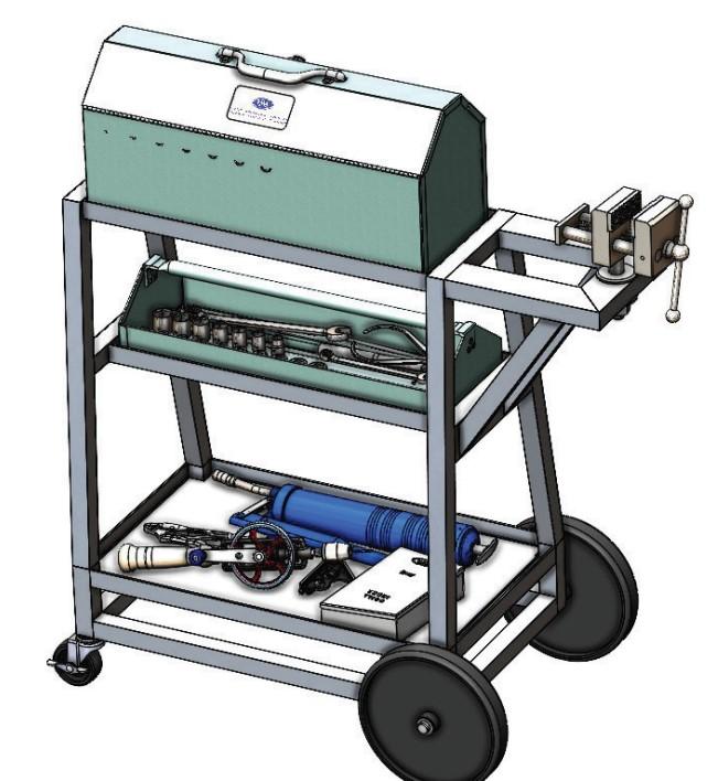
FIGURE 1A. The design for this cart has almost evolved into a product. What could increase its demand?
The cart design shown in Figure 1A has been evolving over the past few episodes. “Wouldn’t it be cool if it were self-propelled?” asks the muse by way of introducing the scenario for this episode.
Preparation of a statement of work (SOW) is routine in the profession of product development. The SOW is essentially a list of requirements, activities, and benchmarks. It supports the budgeting for the project. It outlines what will be achieved and when. If clearly stated, the SOW will define success. Development of a SOW to add muscle to the cart is presented here from a CAD jockey’s perspective.
Rick Chin is an accomplished product developer, inventor, and engineer. He is the author of a product development paradigm that provides structure when facing the uncertain. I believe my success in product development is directly proportional to my adherence to his advice.
To summarize his approach, a brief stage exists in product development when blue sky is the limit. The goal is to discover the ideal, or the absurdly ideal, as he calls it. This is his attention-getting hook for a rather disciplined approach to focused exploration for possible solutions. With a handful of inspired possibilities in mind, winnow towards the achievable. Chin’s method of winnowing is highly recommended. (To learn more about Chin’s approach, visit www.absurdlyideal.com.)
The mechanical revision to the cart’s 3D CAD model will be driven by sensors, motors, electronics, and cables. In the spirit of the absurdly ideal, a team gathers to consider the best that such animation could accomplish.
The steering committee imagines a variety of behaviors for a tool cart. Inspirations include robotic line following, inertial assist, autonomous navigation, and the obedient helper on a telepathic leash.
Our team of visionaries winnow their ideal notions down to one achievable idea that satisfies the opportunity of time—a joystick version. A quick prototype can serve as a test bed for development of a more ideal steering system.
This simple-as-can-be powered cart is to be implemented using off-the-shelf components, perhaps relying heavily on the radio-controlled vehicle industry. Even with the addition to steering by joystick, the cart can be steered manually when there is no power.
Collision is undesirable. The driver is responsible for collision avoidance and detection. The test bed version will rely entirely on the human for obstacle detection. Self-driving versions might introduce the mechanical need for mounting of additional sensors.
One task in preparing the SOW is to quantify the required responses to deflection of the joystick. Proportion-integral-derivative (PID) control logic will be implemented to allow the cart to follow commands in a smooth and agile manner.
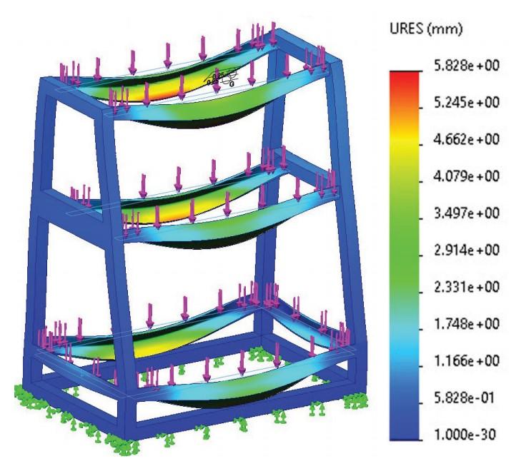
FIGURE 1B. The existing design of the tool cart can carry 270 kg (550 lbs.). A drive system is needed that can move that mass with dexterity.
If an arbitrarily complex sequence of joystick commands is repeated, the objective for an ideal cart could be to execute the same path of motion each time. The committee sets target requirements for an “acceptable” cart—complete a single distance command within 4% and an angle change within ½ degree.
The objective behind rapid response to joystick deflection is to give the operator the sensation of reliable control. That objective translates into a requirement for velocity change within 1/8 sec. (125 ms).
Specification of dexterity—acceleration, speed, braking, precision, and endurance—is part of the required work to be done. The steering committee has provided ideal target dexterity, but reality might require change to those targets:
A requirement emerges for an activity: the discovery of what is available. The benchmark for this is a report on the budget and schedule for specifying a specific and achievable dexterity for the cart. The imagined SOW states that the report will be prepared by a deadline and will present differences from the ideal in detail.
That could be the entire scope of the SOW for adding motors to the cart—discover what can fit and report on how agile the cart would be. Perhaps the achievable level of dexterity is acceptable.
In the event that our visionaries deem the reported solutions to be promising, a subsequent SOW could address the merging of specific off-the-shelf components with the cart’s 3D CAD model.
To specify well, clarity is needed on the requirements. From studies of the existing design (see Figure 1B), the weight and rolling resistance for the cart is known. A list of specifications emerges:
These details constrain the acceptable drive system. With this size wheel, the maximum torque needed to fully accelerate a loaded cart is estimated at 720 newtons (160 ft.-lbs.). To merely keep a fully loaded cart rolling takes only 213 newtons (48 ft.-lbs.) of torque.
The physical size of the cart and the compartment that the drive train must fit into is 8 cm tall by 33 cm wide by 55 cm long (3-1/8 by 13 by 21-1/2 in.).
At this point, the team has enough information to start searching for motors, batteries, cables, and control housing. The task seems to be to cram significant torque into a small suitcase.
The SOW will document the activity of modeling the selected components, perhaps by download or perhaps by reverse engineering. The time is estimated for updating the CAD with product manufacturing information (PMI) and with details for procurement.
With the 3D models of what is to be mounted in hand, the next activity in the SOW is modeling the updated design. There is a need to invent mounting for the drive train with safety and durability in mind.
As used here, a benchmark defines how to identify successful progress. A benchmark states what is to be measured. Each required measurement has clear accept/reject criteria.
While composing an ideal benchmark statement, we recall Kipling’s immortal poem: “I have six honest serving men. (They taught me all I knew.) Their names are What and Why and When and How and Where and Who.”
Here is the benchmark statement: “Before Sept. 1, Gerald Davis is to use internet search and CAD tools to compose a list of off-the-shelf components that can deliver at least 48 ft.-lbs. of torque at 4 RPM, verify that the components fit in the available space, and identify any needed custom gears and belts. This is in preparation for modeling a virtual prototype of a joystick-operated cart.”


The Fabricator is North America's leading magazine for the metal forming and fabricating industry. The magazine delivers the news, technical articles, and case histories that enable fabricators to do their jobs more efficiently. The Fabricator has served the industry since 1970.
start your free subscription
Easily access valuable industry resources now with full access to the digital edition of The Fabricator.

Easily access valuable industry resources now with full access to the digital edition of The Welder.

Easily access valuable industry resources now with full access to the digital edition of The Tube and Pipe Journal.

Easily access valuable industry resources now with full access to the digital edition of The Fabricator en Español.
In this episode of The Fabricator Podcast, Caleb Chamberlain, co-founder and CEO of OSH Cut, discusses his company’s...


