


Contributing Writer
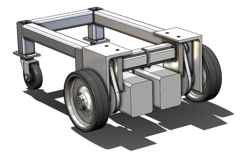
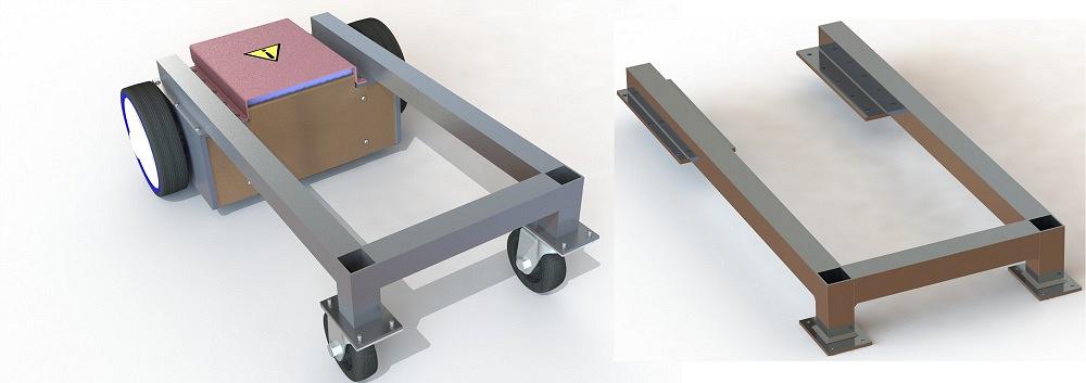
FIGURE 1A. An earlier version of this cart’s frame used large L-shaped extrusions.
Figure 1A shows a motorized cart base. This imaginary shop cart was introduced as a CAD project in the August 2021 episode. A few revisions to the motor’s mounting have been introduced as the design has evolved.
Figure 1B shows an updated model for the frame. The best way to model such a frame seems always to have been the other way. The grass is greener on the other side of the mouse, as it were.
Using our brand of mainstream 3D CAD, a few of the other ways to model it could be:
Briefly, the pros and cons of these techniques are as follows. The multibody part allows all the pieces (bodies) to be visualized as they are developed. The main CAD trick involved: Some of the extruded features are not merged with others.
This creates the multiple (individual) bodies that represent structural elements. The multibody technique keeps all the pieces in a single CAD file. In the old days of floppy disks, that sort of stuff mattered.
Perhaps a more significant “labor savings” of multibody modeling is that the structural members are positioned by their sketched paths (paths in a 3D sketch, perhaps). No additional constraining with mated relationships is needed. Most importantly, bodies in a multibody part are exportable as individual files (STEP, STL, et al) for CAM or fabrication.
The CAD software has a suite of tools (found on the Weldments menu tab) that helpfully generate structural members. Just sketch the path and select the profile. Options exist for corner treatment and profile location. The Weldment tool can also help in other ways, such as with gussets, end caps, weld notes, and cut lists.
Compared to a multibody part, an assembly of parts has a couple of advantages. First, an assembly is easier to animate (by adding mouse-draggable kinematics or movie-like motion studies). Second, assemblies populate a Bill of Materials (BOM), whereas weldments populate a Cut List.
Compared to a Cut List, the BOM (via the components in the assembly) can be more comprehensive (inclusion of nuts, bolts, paint, etc.) but not as automatic as a weldment’s Cut List (which provides handy dimensional lengths).
Side note: CAD has tools that are useful to a fabricator—one who needs accurate flat layouts and cut lengths. CAD also has tools that are useful to produce support materials, such as quality control, itemized assembly, and end user documentation. Perhaps the cut length is more important than the description of the structural member; thus, a weldment’s Cut List would be a better choice than an assembly’s BOM table.
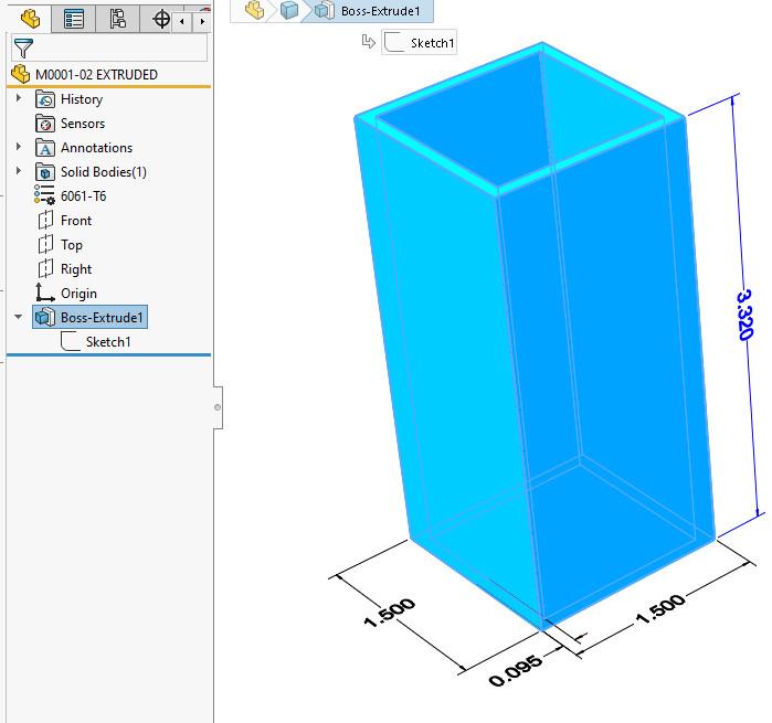
FIGURE 2A. One method of modeling a structural element is to sketch a profile and extrude it some distance. Note eight line segments, three dimensions, and several relationships can be found in the 2D sketch.
How the 3D model evolves, as well as when it can be completed, is constrained by the resources (i.e., CAD skills) on-hand.
Deriving individual parts from a multibody is a matter of some clicks in the menu system. The skills of knowing what to click on and where to find it in the menu, along with the mental gymnastics (CAD hierarchy of master part > derived body > assembly > 2D drawing) can be essential when it comes to sustaining engineering, a fancy way to say “editing and revision for the life of the product.”
There is a foundational skill level that doesn’t employ as many menus. Straightforward has its own merit. That is to say that the creation of 2D sketches and extruding those to make 3D parts will get the job done.
Figure 2A shows a structural element that was modeled using a 2D sketch of a square tube’s inside and outside perimeters. The resulting 2D sketch was extruded to the desired length. To model the frame shown in Figure 1B, this process of extruding individual structural element parts needs to be repeated three times. (Some of the tubes are used twice.)
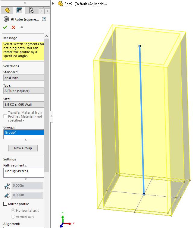
Moving up the fancy scale, Figure 2B shows a structural element modeled using a 2D sketch with just a single line segment of a path down the center of the tube. This is a much easier sketch to create than the preceding example. The Weldment tool is being used here to select a profile from a standard library. This, too, is much easier than sketching.
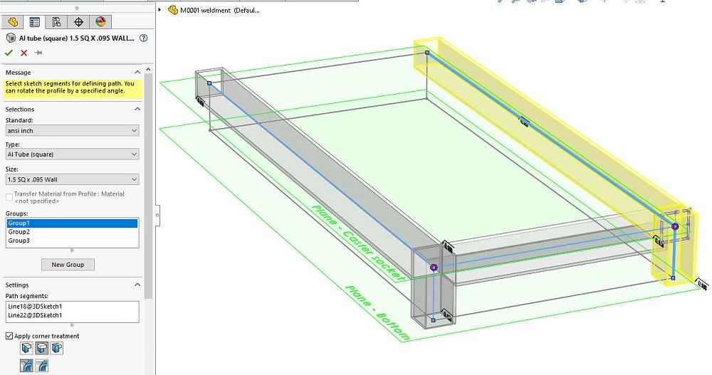
Going all in with fancy, Figure 2C shows a weldment based on a 3D sketch. The line segments are being used as paths for the location of weldment profiles. The line segments are located with relationships to planes (shown in green in Figure 2C). To change the height of the caster socket, change the location of the plane.
Note that the Weldment tool in Figure 2C is properly trimming the corners. The preceding example requires some math to calculate the trimmed length.
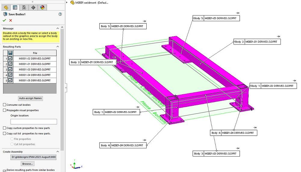
To create an assembly from a multibody weldment, the Save Bodies tool does the job. Figure 2D shows what it looks like after the filenames for the various bodies have been assigned.
Clearly, the best way to model this frame is to set up reference geometry that allows exploration of various heights and relationships. Use that geometry to constrain the routing of structural members in a weldment. Use that weldment’s Cut List to generate a work order. Also use the weldment to create component parts in an assembly to generate assembly and welding instructions.


The Fabricator is North America's leading magazine for the metal forming and fabricating industry. The magazine delivers the news, technical articles, and case histories that enable fabricators to do their jobs more efficiently. The Fabricator has served the industry since 1970.
start your free subscription
Easily access valuable industry resources now with full access to the digital edition of The Fabricator.

Easily access valuable industry resources now with full access to the digital edition of The Welder.

Easily access valuable industry resources now with full access to the digital edition of The Tube and Pipe Journal.

Easily access valuable industry resources now with full access to the digital edition of The Fabricator en Español.
In this episode of The Fabricator Podcast, Caleb Chamberlain, co-founder and CEO of OSH Cut, discusses his company’s...


