


File export fundamentals in structural steel fabrication
Efficiencies gained with detailers and fabricators on the same page

Images: Trimble Inc.
Editor’s Note: The following is based on information from “The Steel Detailer and Client Steel Management Software,” presented at the 2021 NASCC: The Virtual Steel Conference by David Hiddemen, senior sales engineer at Trimble, Structures Division. NASCC is organized by the American Institute of Steel Construction (AISC).
Automation in structural fabrication has helped increase throughput in some incredible ways, but it’s also increased the importance of an often-overlooked element: communication between the steel detailer and fabricator, especially when it comes to exporting and sending files. Automated equipment requires specific kinds of files formatted in specific ways. Missing or incorrect information can put the brakes on job flow, and letting bad information slip through the cracks can have costly consequences. The last thing a fabricator wants is to send the wrong information to incredibly productive equipment, only to be left with mountains of rework or scrap.
Years ago, detailers just provided a drawing. Today, they’re being asked for drawings as well as various kinds of file types exported from detailing software. When fabricators and detailers know the right questions to ask, jobs start to flow seamlessly and painlessly. To uncover those questions starts with knowing the fundamentals, including the basic file types a structural fabricator needs.
The Basics of DSTV
The DSTV format is an industrial standard defined by the German Steel Construction Association (Deutsche Stahlbau-Verband). The file format (with the “.NC1” suffix) is for feeding data to structural fabrication machines and is used by nearly every machine brand. Exceptions exist for certain kinds of punching machines and other specialty equipment. But for the most part, whatever machine you’re feeding, DSTV will likely work.
Although DSTV is a standard, at times machines may interpret DSTV files differently. To really understand the DSTV file type, you need to understand what it’s really doing and why it’s structured the way it is. This way, if there’s an issue with the DSTV file format, you can diagnose the problem.
At a fundamental level, DSTV is simply a text file that defines the part and the actions to take on each face of that part. Each type of part in structural fab is defined with specific letters in the text file:
The file incorporates X-Y coordinates that define the part shape, instructing the machine to perform a task to the desired face. Those coordinates basically say, “This is the shape I want the part to be after you complete the task.”
Consider a simple beam (with an “I” designation in the file) that has copes on the top flanges on each end (see Figure 2). All these processes will be happening on different faces. In this example, the copes will be defined by specific coordinates on the front (v) and top (o) faces. Since the coping operation removes some flange material, the top face will be smaller than the bottom face (u). The file format uses the same description method for bolts, holes, slots, different types of marking—essentially, any operation that a machine performs on the workpiece.
Is the DSTV File Correct?
The export to DSTV happens automatically, so you needn’t dive into the weeds of every designation and coordinate. What’s important is knowing that the DSTV is correct for the machine on the structural fabrication shop floor.
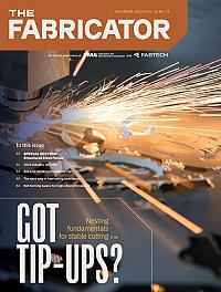
Here, free DSTV viewers can help tremendously. ProCAM Lite from HGG and Steel Projects CAD Viewer from Ficep are just two examples, and you can likely find a few more online. These viewers take that DSTV file and show you a picture of the actual part that all those individual text-based commands create. So, you can verify, “Yes, it is creating those copes where I expected them to be.”
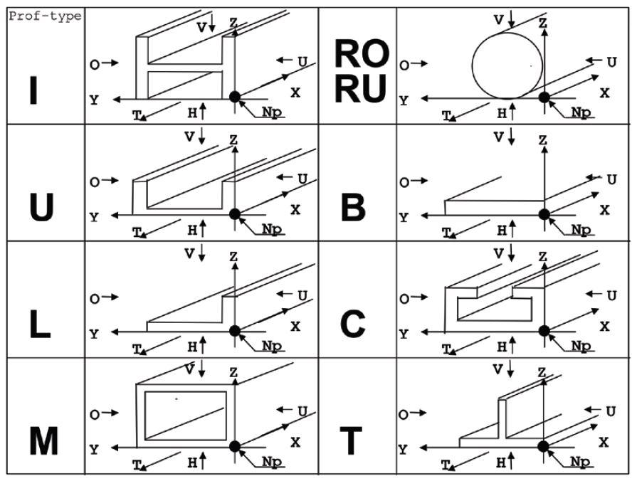
FIGURE 1. As part of the DSTV file standard, different letters designate different part shapes. Knowing the basics of how these text files are structured can help you when troubleshooting problems. (This is for illustration purposes only. Complete information can be found by accessing the latest DSTV standard. More information can be found at support.tekla.com.)
The most important thing is to use more than one file viewer. Again, DSTV files are sometimes interpreted differently, and so running them through multiple DSTV file viewers can sometimes help catch those different interpretations. If a file is correct in one viewer but incorrect in another, some troubleshooting might be in order. This is where communication with the fabricator is critical.
Where’s the Radius?
Because DSTV is a standard format, you can’t tweak many elements, but you can make slight adjustments. One has to do with copes. Your model might have a cope with a hard 90-degree angle—but that creates a weak point in the metal, and you really don’t want that in the final fabricated piece. You really need a radius. The same applies to web penetrations and other geometries cut into the structural beam.
In detailing software, you can check an option that basically says, “When you find a hard corner, add in this radius.” You might have modeled those radii previously, but if you do happen to miss any, checking the DSTV option for radius corners can catch them (see Figure 3).
Machine-specific information comes into play here. Some machines, for instance, drill holes first and then cut the radius to that hole, and radius options in detailing software can help account for that. Once you’ve designated your option, you can use a DSTV viewer to ensure the option came across in the file as expected.
How Far Can You Cut the Web?
Perhaps even more critical are the necessary clearances you need to account for areas where the machine’s cutting tools can’t reach, particularly the area where the web intersects the flange. How close you can cut a web to an underside of a flange will depend on the machine you’re working with. In software, you can find a DSTV option descriptor of “the distance within the flange where the web isn’t cut,” or something similar.
Picture a tool head that cuts a rathole for a full moment prep. The tool head can get only so close when cutting the web before it crashes into the flange. You might have it modeled to where the section is cut all the way to the edge of the web. In this case, you need to accommodate for the real world and the specific machine you’re using. How close can your machine get?
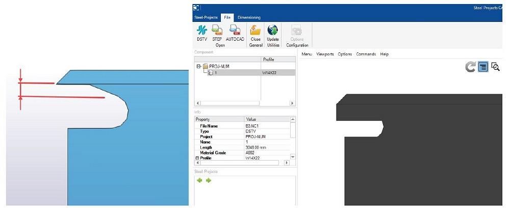
Here is where good communication between detailing and fabrication really pays off. Different machines have different capabilities. You need to know what those capabilities are so you can adjust the cut, making it stop before it hits the critical dimension (see Figure 4). This is by far the No. 1 adjustment detailers and fabricators make to accommodate different machines.
Piece Identifiers
Fabricators today often have their machines stamp or scribe their parts with identifiers and layout indicators, and detailing software has a setting to incorporate these instructions into a DSTV file. If the fab shop works with older machines that can’t do this, you don’t want the hard stamp or piece marking option selected in the software. But if it’s requested, you can enable it.
Some fabricators have the piece mark, others incorporate job numbers and even the erection sequence, and you can choose to scribe these options in software. You also can select the size and location of the text. Again, you can run it through a DSTV file viewer to make sure the text appears as intended (see Figure 5). It’s possible that you mistakenly instructed the system to scribe a mark on a flange that’s been removed; you might have mistakenly selected the mark location. Running a DSTV file viewer can help prevent these mistakes from reaching the fab shop floor.
Pop Marks and Scribing
A fabricator might also use a machine’s scribing function to create locating marks for welding and other secondary operations. This effectively automates the layout function. No longer will workers need to get out their tape measure and mark work manually with a grease pencil.
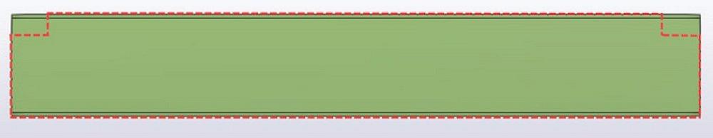
FIGURE 2. In this example, the final shape includes coped sections of the top flange (shown in red) that are defined in the DSTV file with specific coordinates on defined faces.
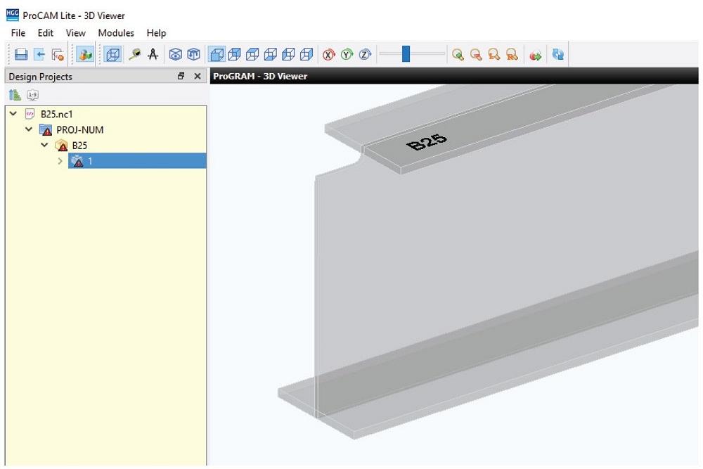
Machines also create so-called “pop marks,” which are essentially a dot created by the machine spindle, read as a zero-inch-diameter hole from the NC data. Picture a tool “buzzing” the workpiece quickly to create a simple dot. They can be located on the part edge, on a shear tab in line with holes—anywhere that can help fit-up personnel locate workpieces properly. For instance, hole locations might be more critical than the edge of the plate, so you’ll need to adjust settings to ensure the mark is in line with specific holes, not the edge of the plate. On a stiffener plate, pop marks can mark the centerline. Software options can accommodate all of this and incorporate it into that DSTV file export, which (again) can be checked with a DSTV file viewer (see Figure 6).
Years ago, pop marks were about as advanced as most fab shops got when it came to machines marking layout and location points on a workpiece. Today, though, most modern equipment has highly advanced marking capabilities. Depending on the machine brand, they might call it scribing, layout marks, or contour marks. They inscribe marks (sometimes even using lasers) that can, for instance, locate pans on stair stringers, stiffener piece marks on beam webs, and more. Marks can be scribed on multiple pieces to facilitate an error-proof assembly.
These can involve full or partial outlines of the parts to be placed. Full outlines are easiest to see, but they also take time for the machine to scribe them. So, a shop might choose to have just a partial outline, showing corner locations or other elements that give assemblers the information they need without consuming excessive machine time.
Here again, the DSTV options abound. Where should they be created and what should they include? Should they include only parts that are welded and assembled in the shop, or should they include field-assembled parts as well? And again, keep one of those DSTV viewers handy to double-check the part.
Questions to Ask
To make that seamless flow of information a reality, ask the following questions—before a project begins:
- What type and brand of machines are you using?
- Do you require pop marks or scribing/contour marking, and to what extent (weighing marking time with what assemblers need)?
- What file types do you require?
- Do you need access to the model?
STEP Up to 3D
Detailing software can export STEP and IGES file types, usually associated with modeling software like SolidWorks or Inventor. In the structural arena, they’re usually requested for tube cutting and bending, especially for handrails.
Many detailing operations do not have 3D CAD, though. If that’s the case for your operation, be sure to preview these file types with a CAD file viewer like FreeCAD. This ensures that what you’re exporting incorporates everything the fab shop floor needs. Also, if you design a component in multiple sections—such as three sections of a handrail that will be fabricated as one piece—be sure the file export incorporates all the sections that will make up that one fabricated tube.
It’s Just a DXF, Right?
Ubiquitous in sheet metal and plate cutting, in the structural fabrication arena the DXF file is usually read by plasma cutting tables. And sure, exporting a DXF might not seem like a big deal, but like with the DSTV file, you still need to ask the right questions.
For instance, be sure everyone is on the same page when it comes to layer names and colors. If you export or miscommunicate layer information, the machine may not properly read the file. How are holes and slots notated on the DXF? Some DXF file exports have crosshairs over each hole, and some cutting machines don’t read them well. Also, how do the shop’s plate cutting machines handle contours defined as lines and arcs, versus polylines? Depending on the software some machines use, the fabricator may require one or the other. It all boils down to knowing what data a fabricator needs to process high-quality plate as smoothly and effectively as possible.
About XML
Everyone in the structural arena today seems to be talking about it. “We need an XML file!” That’s fine, but what kind of XML file? XML really is just a method of formatting data—recipes, discographies of your favorite bands, anything.
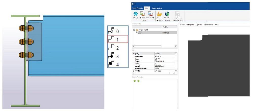
FIGURE 3. In most cases, copes will have a radius (exaggerated here for clarity) instead of a hard 90-degree corner, and detailing software options for DSTV file exports can automatically apply them. They also can incorporate the specific ways machines create those radii, including specific hole drilling and cutting sequences.
In structural fabrication, XML today is used to package both production management and CNC file information. In some cases, an XML file can be bidirectional. That is, a detailer can send an XML file to the structural fabricator, who not only uses but also adds to it, feeding the package back to the detailer. When asked for XML, it’s important to know exactly what software the file is being used for. The result: better, streamlined communication between the detailer and fabricator.
Creating a Seamless Link
These days, some proprietary systems from certain machine manufacturers actually can link directly with detailing software and pull out the information they need (though this usually works only for structural fabricators with some in-house detailing capability). Other proprietary platforms incorporate various information about parts as they flow through the shop, the idea being that the more information a burn table or beam processing machine has about every job, the more effective it can be.
The idea also promotes a seamless flow of information, from detailing to order processing to the machines on the fab shop floor, and, finally, to the field. Such seamless flow can happen only when fabricators and detailers are on the same page, even with generic files like DSTV. No matter the software package, the file export types, or the machines on the floor, the better detailers communicate with fabricators, early and often, the smoother the actual fabrication process will be.
About the Publication
subscribe now

The Fabricator is North America's leading magazine for the metal forming and fabricating industry. The magazine delivers the news, technical articles, and case histories that enable fabricators to do their jobs more efficiently. The Fabricator has served the industry since 1970.
start your free subscription- Stay connected from anywhere

Easily access valuable industry resources now with full access to the digital edition of The Fabricator.

Easily access valuable industry resources now with full access to the digital edition of The Welder.

Easily access valuable industry resources now with full access to the digital edition of The Tube and Pipe Journal.

Easily access valuable industry resources now with full access to the digital edition of The Fabricator en Español.
- Podcasting

In this episode of The Fabricator Podcast, Caleb Chamberlain, co-founder and CEO of OSH Cut, discusses his company’s...
- Trending Articles
1
Tips for creating sheet metal tubes with perforations

2
Are two heads better than one in fiber laser cutting?

3
Supporting the metal fabricating industry through FMA

4
JM Steel triples capacity for solar energy projects at Pennsylvania facility

5
Omco Solar opens second Alabama manufacturing facility
