


Contributing Writer

Getty Images
Editor's Note: If you would like to download the 3D CAD files associated with this column, click here.
An assembled and exploded tote box tray is shown in Figure 1A. This design requires spot welding for the end plates and dividers. Riveting is specified for the handle. This project caught the attention of Reader Rick when he saw it in the February 2021 episode of this column. He observed that the end panels, as separate parts, introduce avoidable complexity and weakness.
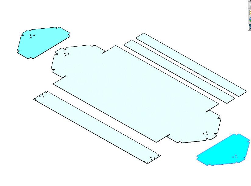
His suggestion eliminates two parts from the flat nest, highlighted in Figure 1B. The frame floor and tray ends are to be bent from a single piece of metal. We shall explore Rick’s suggestion.
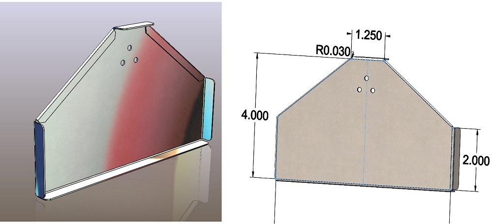
Figure 2A shows legacy features that carry forward into the new design. We will keep the holes and the top flange for the handle attachment. The hemmed edges provide some safety and stiffness, so we’ll keep those. And the vertical flanges help keep things from falling out of the tray.
As foreshadowing, this change is going to be modeled as a sheet metal flange, followed by sheet metal flanges, followed by a hem. That result will be mirrored and mirrored to complete the tray. There are many alternative methods for modeling this project. This demo is trying to show a shortest-path collection of CAD techniques.
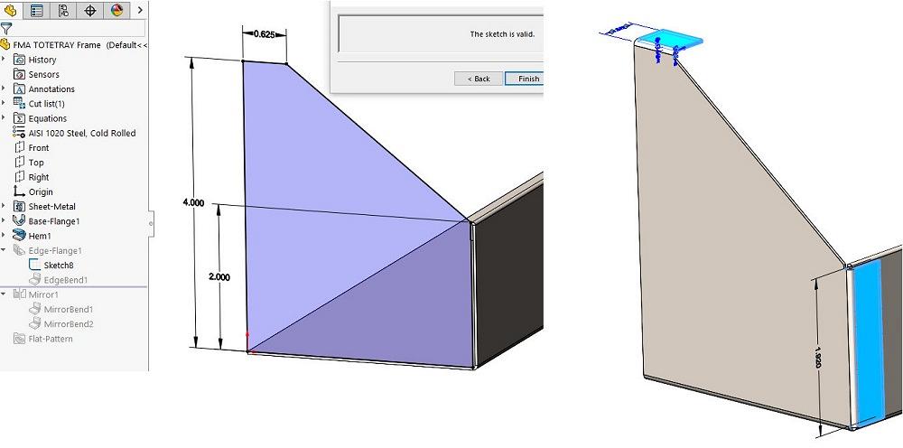
The sketch for a sheet metal flange is shown to the left in Figure 2B (menu path to this sketch is Sheet Metal>Edge Flange>Edit Flange Profile). The sketch roughly matches our legacy 4-in. overall height and 1.25-in.-wide handle tab.
The two other legacy flanges are modeled as a single edge flange feature, shown with highlight to the right in Figure 2B. The author went with two flanges in a single feature because they share the same depth. It might be clearer for future editing to have modeled these as separate features.
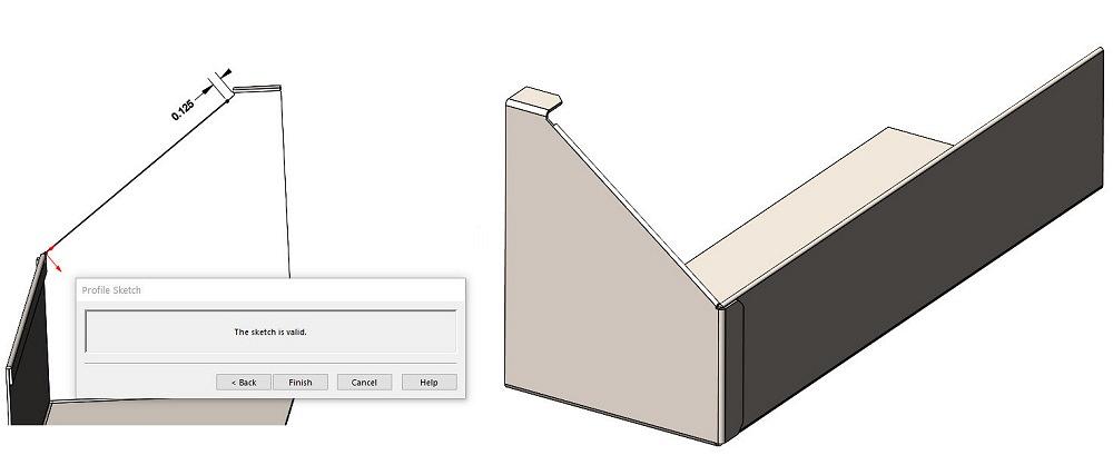
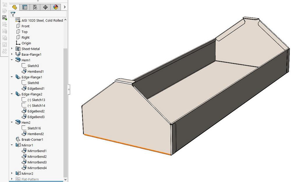
The next legacy item is the hemmed stiffener along the diagonal edge. Figure 3A shows the sketch for the hem feature and the completed hem. The hem’s sketch was edited for good result in the flat layout. Figure 3B shows the sheet metal tray frame after two mirroring features are completed.
The holes for handle rivets are the next task.
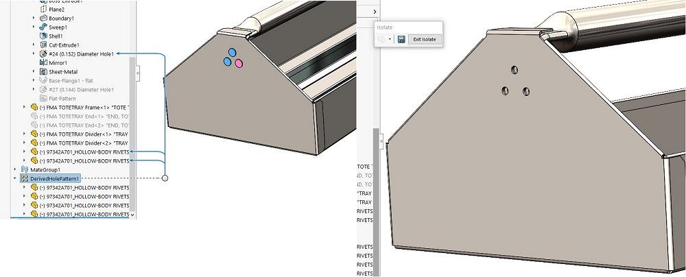
The new unibody sheet metal frame is shown in Figure 4A. Magically, the rivets shown (to the left) are passing through the sheet metal shown in Figure 3B. As a side note for this demo, the rivets were modeled as a derived pattern based on the hole pattern in the handle part.
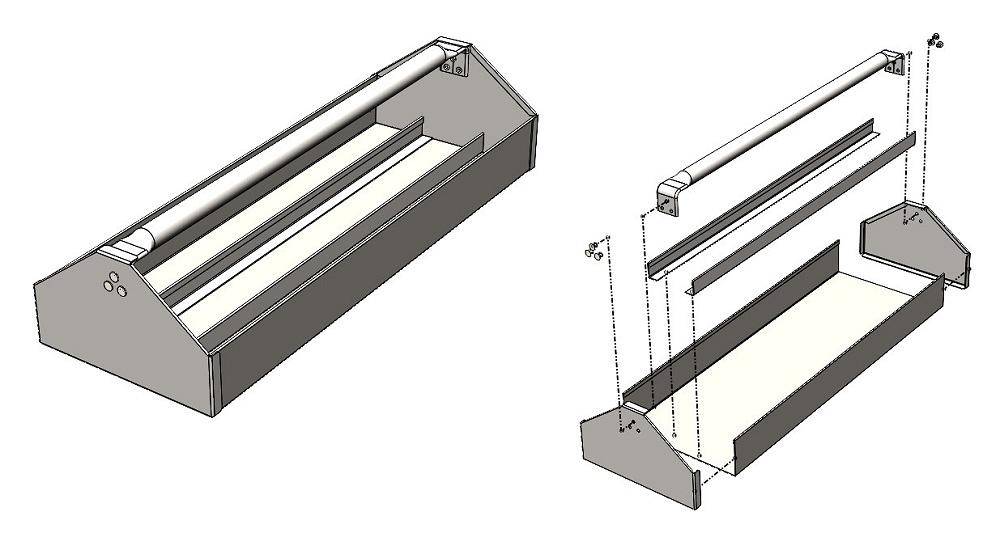
FIGURE 1A. This tote box tray (shown assembled to the left and exploded to the right) has separate end pieces that require welding. Why not make them part of the floor to start with?
To demonstrate a solution to a design intent, the rivet holes (to the right in Figure 4A) were created using an Assembly Feature (Insert>Features>Assembly Feature>Hole>Hole Wizard). The setting for “propagate to selected” is selected, and only the tray gets the treatment.
The design intent for the rivets is to have the handle’s design control the location of its rivets in the frame. The handle design is suspect because of its arcane method of construction.
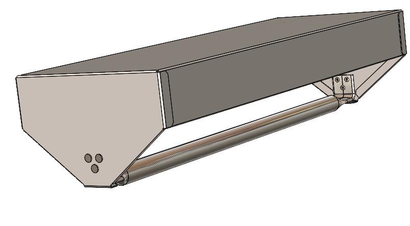
The completed tray, shown in Figure 4B, has a lovely unibody construction. Perhaps the corners are spot welded, or perhaps the handle is enough to tie this box-kite frame together rigidly.So now we chat to see if we got Rick’s suggestion right. And ponder upon change for the better.
Hemming on a press brake is dramatic, requiring lots of time wildly flopping sheet metal. While it is not so bad on a folder-style bender, hemming is still at least a two-step process—make an acute bend and then spank it down to complete the 180-degree bend.
With drama in mind, the separate end pieces, being smaller flat blank pieces, might have been easier to fabricate than the unibody version is. Even though the welding adds time, much less time is spent part handling during the origami stage.
Less welding is always a blessing. Fewer seams mean fewer leaks. The bends add floor strength while reducing the overlap weight. Having fewer parts on the BOM also is a tremendous improvement.
Could we apply this same design inspiration to the main box? Would the box depth be too much for the brake? Will the handle be redesigned?


The Fabricator is North America's leading magazine for the metal forming and fabricating industry. The magazine delivers the news, technical articles, and case histories that enable fabricators to do their jobs more efficiently. The Fabricator has served the industry since 1970.
start your free subscription
Easily access valuable industry resources now with full access to the digital edition of The Fabricator.

Easily access valuable industry resources now with full access to the digital edition of The Welder.

Easily access valuable industry resources now with full access to the digital edition of The Tube and Pipe Journal.

Easily access valuable industry resources now with full access to the digital edition of The Fabricator en Español.
In this episode of The Fabricator Podcast, Caleb Chamberlain, co-founder and CEO of OSH Cut, discusses his company’s...


