


Contributing Writer

CAD expert Gerald Davis walks through the design and documentation of a welded frame. Getty Images
Editor's Note: If you would like to download the 3D CAD files associated with this column, click here.
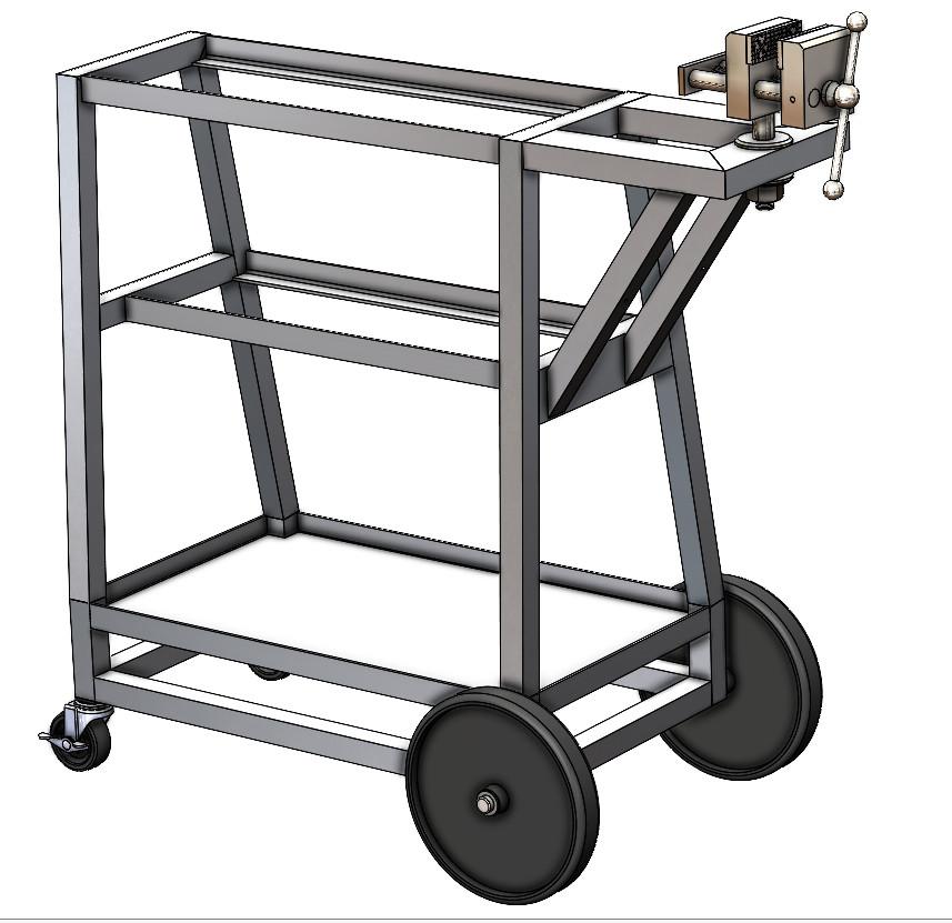
The cart shown in Figure 1 was rolled about in the previous episode. The four little casters skate nicely. Fortunately for this episode, the design needs to evolve. It lacks a vise. Out of concern for load and impact, two of the casters are to be replaced with hard wheels.
Here’s a CAD tip: A familiar object gives scale and lends meaning when presenting a design. The myriad tools on the cart in this example are perhaps distracting clutter. Moderation in all things.
The cart, without the clutter of accessories, is shown in Figure 2A. In the real world, this is how the cart would be assembled.
To prioritize CAD labor, the casters and wheels, axle caps, and vise are off-the-shelf items. They will get the minimum amount of effort. The 0.5-in.-diameter axle is cut to length but is otherwise common steel rod. The documentation for these items is primarily textual information to support procurement. Downloaded or representative models work expeditiously.
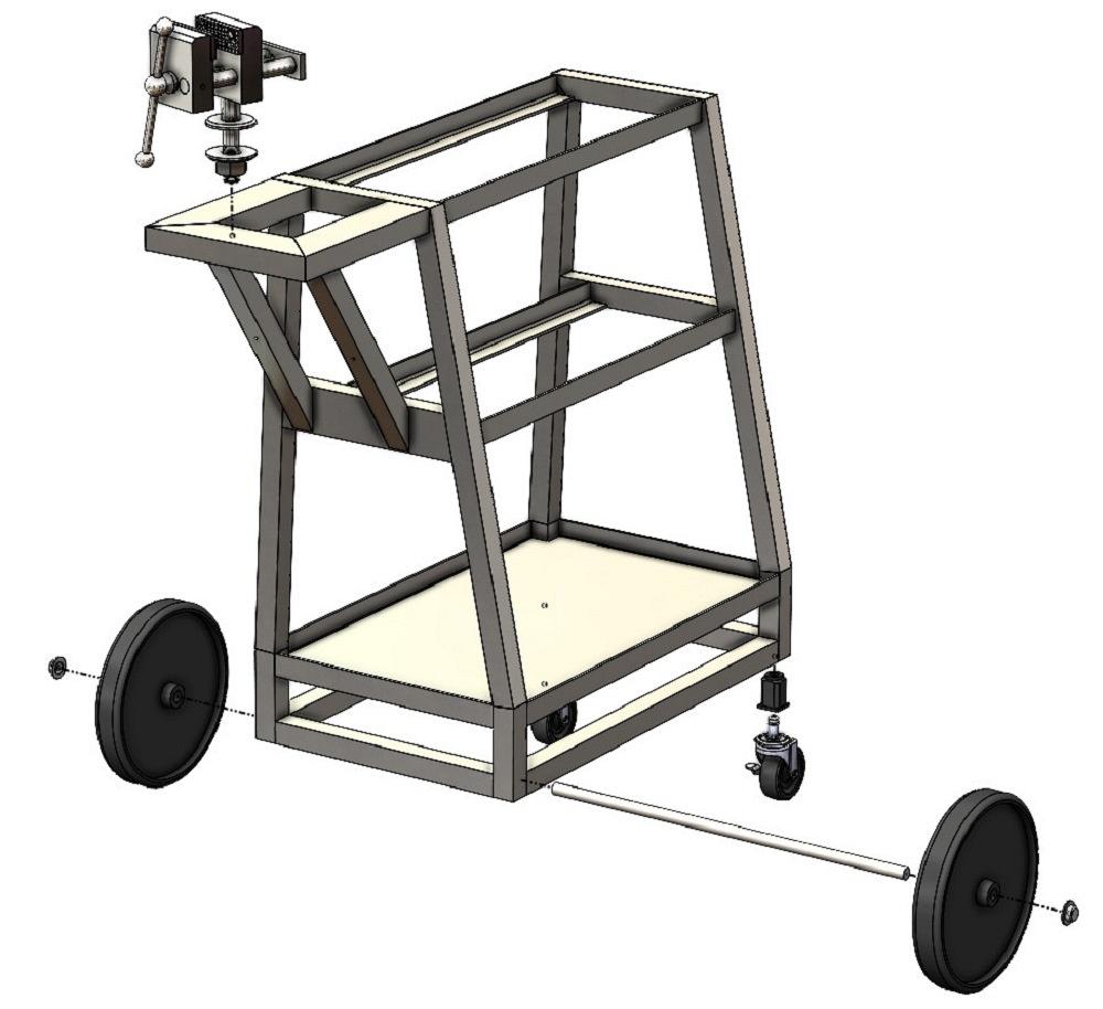
The thrill, in terms of design fidelity, is the welded frame. Figure 2B picks up where the previous episode left off. We now know where the missing holes should be. Modeling holes in a weldment is not difficult, but many paths can be taken through the CAD menu of tools, all delivering alternative outcomes. Here we contrast assembly with multibody modeling.
Let’s pause for a moment to discuss terminology: In the brand of CAD being demonstrated, CAD assemblies are like matryoshka nested dolls. Components that make up assemblies can be assemblies or parts. CAD weldments start out life as multibody parts, a different way to represent a real-world assembly.
As with any multibody part, the bodies in a weldment can be saved to external files to create an assembly of parts. This results in components that are parametrically linked to the weldment part.
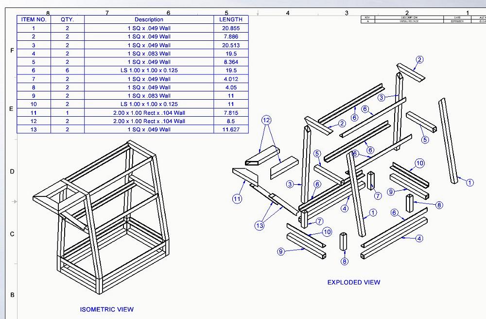
Figure 3 shows a drawing for a multibody weldment. The table shown is an inserted Cut List. It is generated from the bodies in the part. Cut List tables have power that bill of materials (BOM) tables lack—an automatically generated list of lengths.
The Cut List table displays information from solid bodies found in a part. This is distinctly different from a BOM table, which displays information from the components found in an assembly. As a matter of drafting standard/style, the BOM table and assembly method are perhaps more familiar than Cut List and multibody documentation.
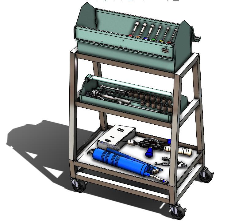
FIGURE 1. Weldment CAD techniques used to design this cart with four casters were discussed in the previous episode of Precision Matters.
We have a choice between Cut List and BOM table. Either way, the weldment needs holes.
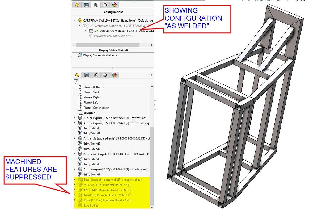
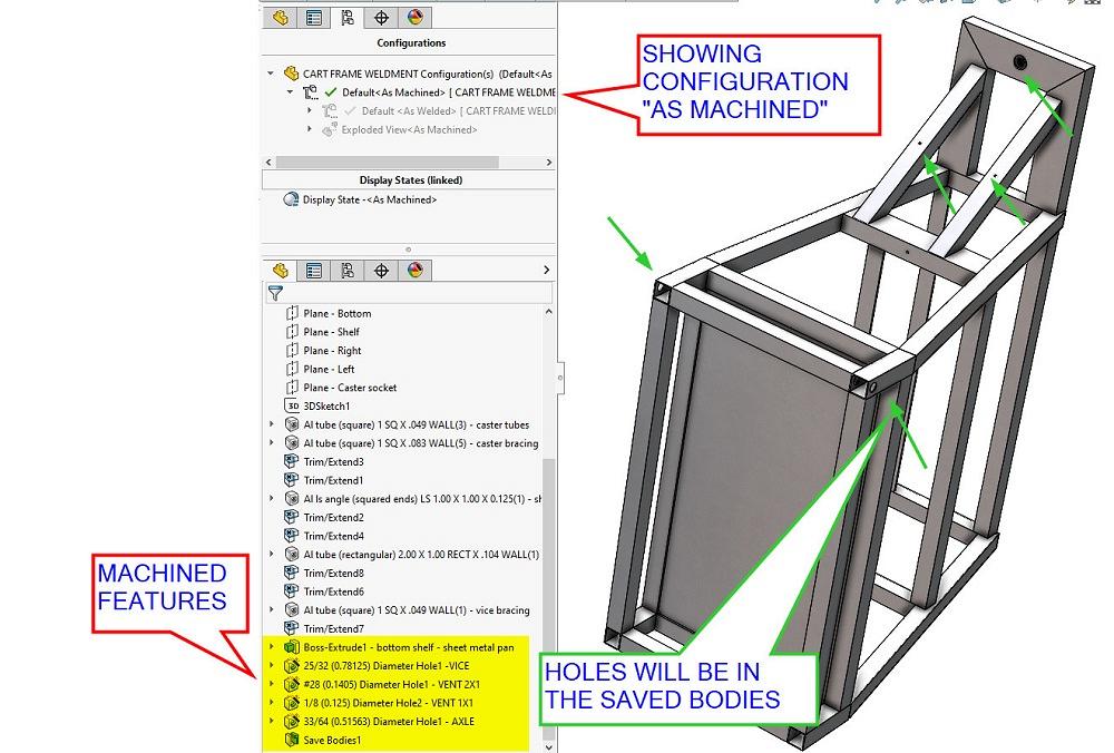
Do these holes get drilled before or after welding? The CAD brand being discussed has a system setting that makes a distinction between as welded and as machined. If automatic is preferred, when a weldment is created, the CAD will create two configurations. The idea is that features that are added after welding are suppressed in the as welded configuration and are revealed only in the as machined configuration.
In Figure 4A, the Default
In Figure 4B, the Default
If the Cut List table approach to documentation will suffice in your shop, then the sldprt as multibody weldment cut list technique in Figure 3 is perhaps the end of this episode. Not shown are the several drawing sheets to show the completed size of the frame with hole locations.
If a BOM table is needed instead of a Cut List, the bodies in the weldment can be “exported”—saved as external part files and used in an assembly. Then that assembly can be used to make a BOM to replace the Cut List.
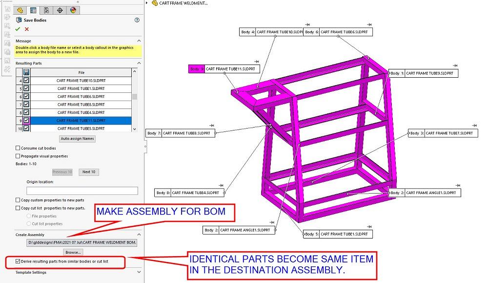
The tool that saves bodies can be commanded to create an assembly of the parts it creates as it creates them.
Figure 5A is a screen shot of the setup used to create the assembly. The setup includes assigning names to all of the sldprt files that will be created. Of particular usefulness in the Save Bodies tool is the checkbox that recognizes identical components. When checked, the resulting BOM is tidy. The same item is used twice instead of as two individuals that are twins.
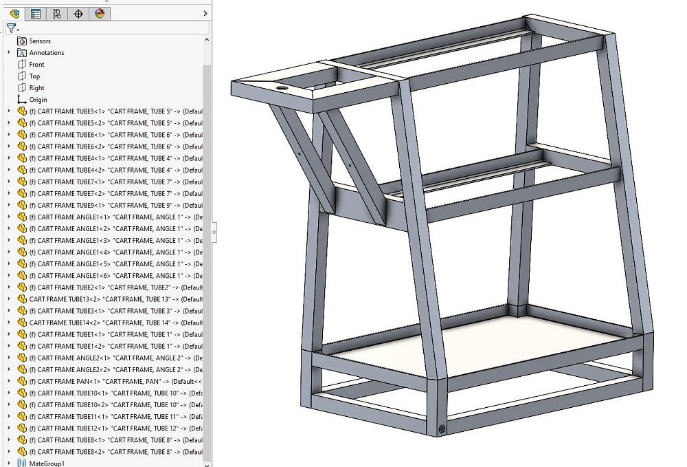
Figure 5B shows the newly created assembly. Features in the as machined configuration have been inherited from the weldment’s bodies. If we squint really hard at Figure 4B, we see a Save Bodies feature in the as machined configuration. The as welded configuration doesn’t save bodies or create assemblies in this example.
The action of the Save Bodies means that any change made to the solid bodies in this part will be propagated into the saved components. Caution: Save Bodies will replace existing part files and might be a nuisance to PMI that gets overwritten with blanks.
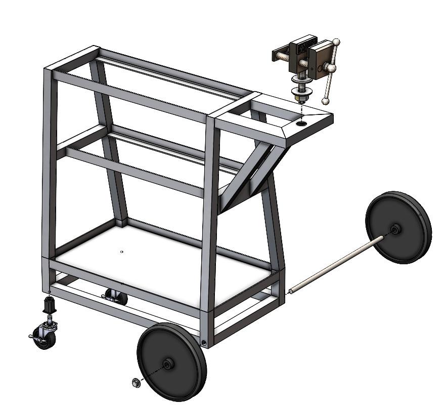
FIGURE 2A. The connected components of the cart are modeled as an assembly of frame weldment, casters and sockets, wheels, axle and axle caps, and vise.
If the method of documentation using a BOM is good, with the exception of missing drawings for hole locations, this episode has ended. However, we didn’t answer the question. Does the documentation need to show the holes in the parts that are welded, or should it show the holes after the parts are welded?
In Figure 5B, the holes exist in the parts before welding. The piece part drawings will show holes. Maybe that is good. Maybe not. If holes happen after welding, the answer perhaps gets punted to the new assembly.
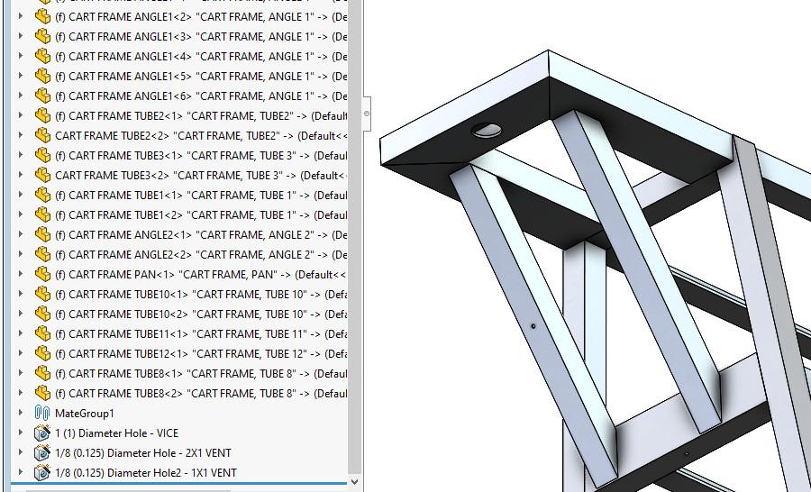
The CAD brand being discussed features a suite of tools called Assembly Features. To demonstrate one of these tools, we have used the Hole Wizard as an Assembly Feature in Figure 6A to drill a vent hole in the brace.
The intent is pressure relief to make closed-seam welding of this tube easier. When set up, the vent hole was not propagated to the part. It exists only at the assembly level. The hole will not show up in the part’s drawing.
Note in Figure 6A that as a consequence of nonpropagation, only one of the two braces has a vent hole. The Hole Wizard’s sketch could be edited to add that cutout.
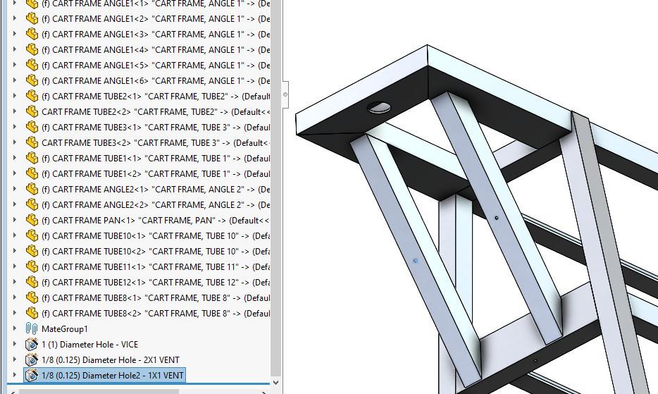
In this scenario it is desirable to show the holes on the piece part drawings. The Assembly Cut shall be set to propagate to the target part(s).
Figure 6B shows the result of that propagation setting. Since the same part is used twice in the assembly, when the cut propagates to the part, all copies of that part will show the propagation too.
The difference between Figure 2B and Figure 7 is that 2B shows a part (weldment) and the other shows an assembly (weldment) that is parametrically linked to a part (weldment).
One final CAD tip: To keep the master part file from getting separated from its children, include the master part weldment as a hidden component in the assembly weldment (and exclude it from the BOM to keep this our little secret).


The Fabricator is North America's leading magazine for the metal forming and fabricating industry. The magazine delivers the news, technical articles, and case histories that enable fabricators to do their jobs more efficiently. The Fabricator has served the industry since 1970.
start your free subscription
Easily access valuable industry resources now with full access to the digital edition of The Fabricator.

Easily access valuable industry resources now with full access to the digital edition of The Welder.

Easily access valuable industry resources now with full access to the digital edition of The Tube and Pipe Journal.

Easily access valuable industry resources now with full access to the digital edition of The Fabricator en Español.
In this episode of The Fabricator Podcast, Caleb Chamberlain, co-founder and CEO of OSH Cut, discusses his company’s...


