


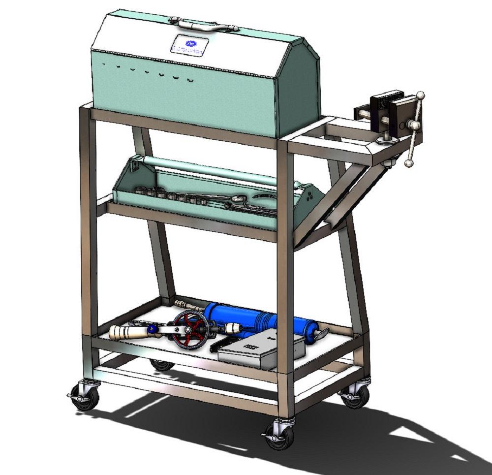
Contributing Writer
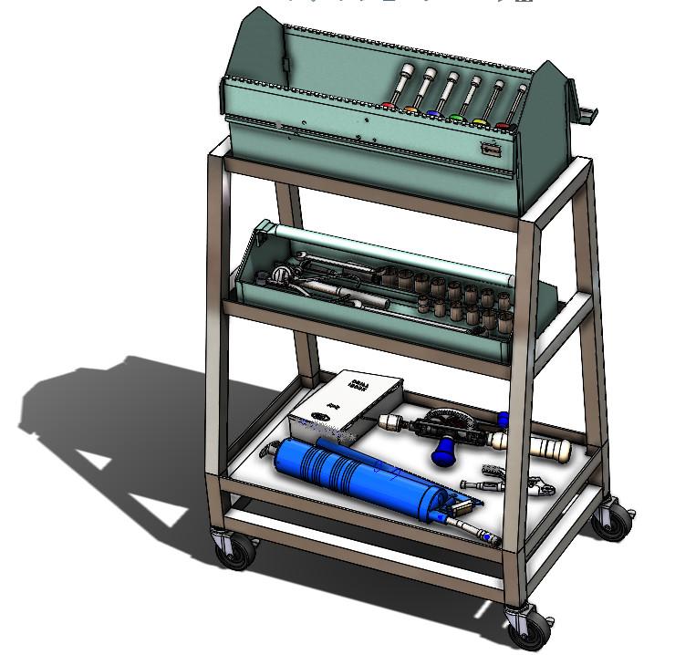
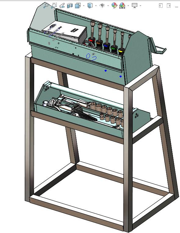
FIGURE 1. The model for this cart will be useful for future discussion of weldments and vent holes.
Editor's Note: If you would like to download the 3D CAD files associated with this column, click here.
The FMA tote box cart shown in Figure 1 is termed a weldment in the brand of 3D CAD being used here. Discussion of weldments was inspired by a real-life project that involved adding vent holes. (When tubing can be sealed into a functional balloon by welding all seams closed, strategic placement of vent holes is beneficial to prevent pressure hazard and flawed weld beads and control corrosion.)
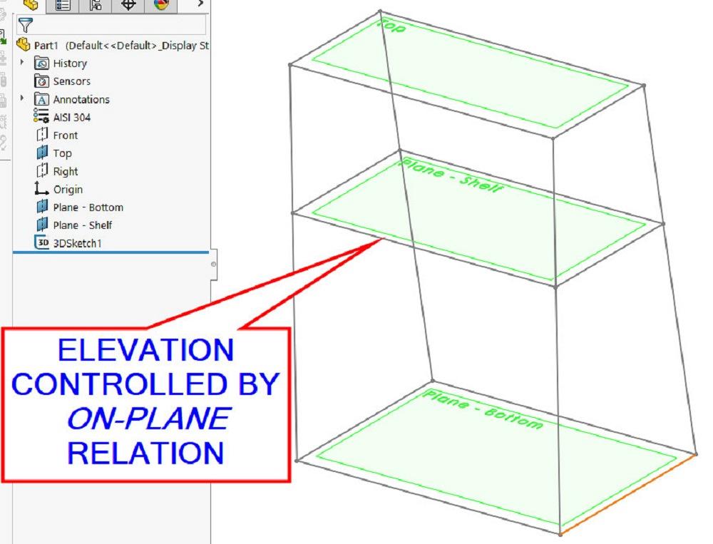
If you will, the cart in Figure 1 does not exist yet. Such a model of a cart needs invention so it can be vented. The CAD modeling trail presented here will use reference geometry (Figure 2A) to control a 3D sketch (Figure 2B). Some or all of the line segments in the 3D sketch will define the weldment’s structural members (Figure 2C). Referring to Figure 2B, the locations of the reference planes set the elevation relative to the top plane down to the bottom shelf. The middle shelf’s elevation is defined at some distance down from the top to allow for reach access.
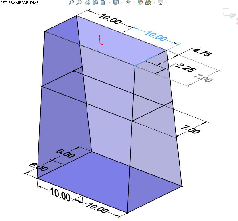
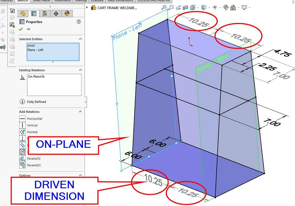
In Figure 2D, sketch elements are constrained by on-plane relationships as well as with dimensioned relationships. The modeling decision to use dimensions rather than some form of external reference geometry is a matter of exploration.
As this design evolves, the elevations are most likely to change. Convenient relocation of a single plane to effectively relocate several individual sketch segments can be a blessing.
If editing the location is less likely, then perhaps intuitive meaning of the dimension takes priority. In this example, the FMA tote box constrains the practical shelf size. The size of these shelves is likely to be static. Those features have been constrained with dimensions instead of with external geometry.
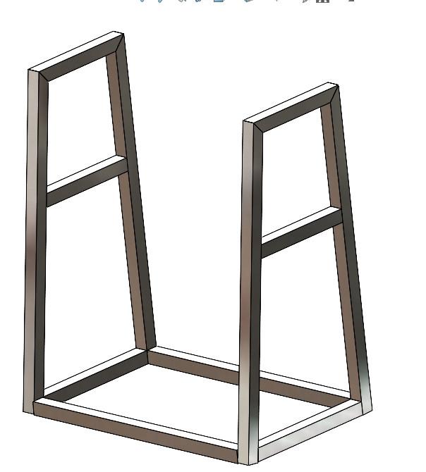
In the real world, the availability and cost of material being welded are important design considerations. The loaded FMA tote box probably will never weigh more than 30 lbs. In the worst case, this cart’s frame might be inviting us to use it as a step stool, so it might see 300-lb. loading. As a starting point, Figure 3A shows a suitable cart frame made exclusively from 1-in. square aluminum tubing. Perhaps only one kind of material would be simple and cost-effective. Or not.
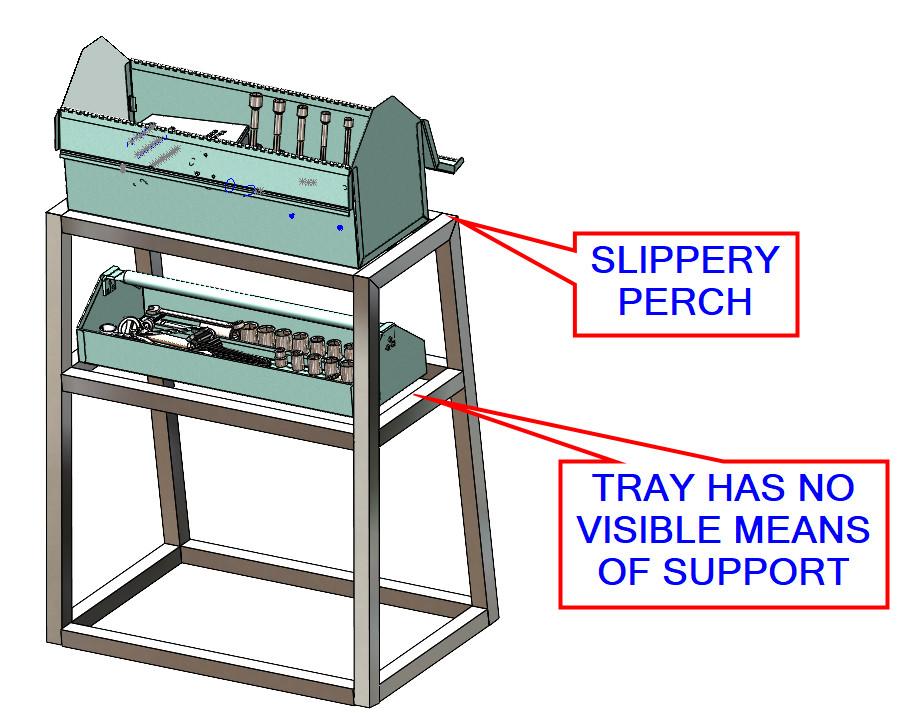
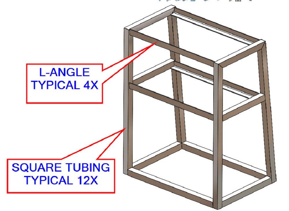
The problem shown by our first test fit is that the tray shelf does not support the tray, and the box might easily slide off of the top shelf. In remedy, Figure 3B shows the shelf design evolution. Some of the structural members changed from tubing to angle. A design goal has been met—to securely cart the box and tray.
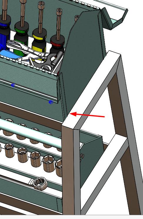
The second test fit, shown in Figure 3C, reveals that the tray is now sitting pretty. The tray is small enough to fit inside the box, so it fits inside the shelf nicely.The top shelf’s fit is excessively cozy. Figure 3D is a closeup view of the problem. The box is 20-in. wide, and the cart is 20-in. narrow. The result is not practical in this project.
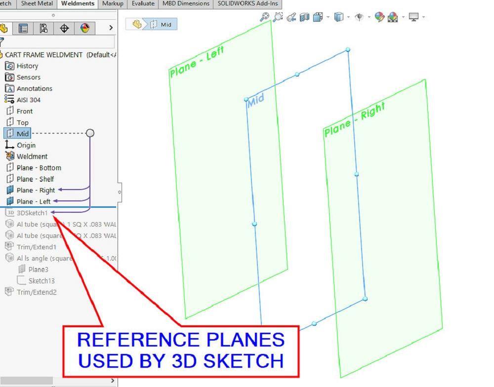
FIGURE 2A. Reference planes are easy to edit with a mouse gesture. Conveniently, all sketch elements that are constrained to a plane will follow that plane’s location. CAD minutiae: Reference planes that are to control the shape of the cart must appear in the Feature manager prior to the 3D sketch.
To fix it, we shall edit the 3D sketch to widen the weldment. Figure 3E shows the revised 3D sketch. New left/right planes (recall Figure 2D) replace the 10-in. dimensions in the 3D sketch.
Those obsolete/conflicting dimensions for width have been set to driven for show and tell as opposed to simply deleting them. The sketch elements are constrained by on-plane relationships. The driven dimensions now report 10.25 in. from midplane for a 20.50 in. width.
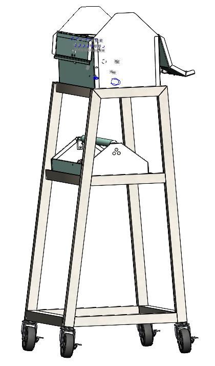
Figure 4A shows the third test fit, this time with casters too. The box and tray both lift in and out of their shelves. Each of the four casters plugs into a plastic socket that is sized to wedge into the ID of the square tubing.
The crowd in the gallery cheers. The design is shippable. However, the casters are cambered badly. This cart will be unruly to steer.
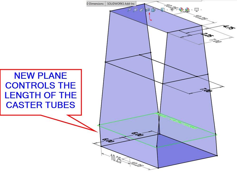
As we address this problem, another reference plane comes into existence, and the external references in the 3D sketch are edited as shown in Figure 4B. Short vertical line segments are about to define the caster sockets.
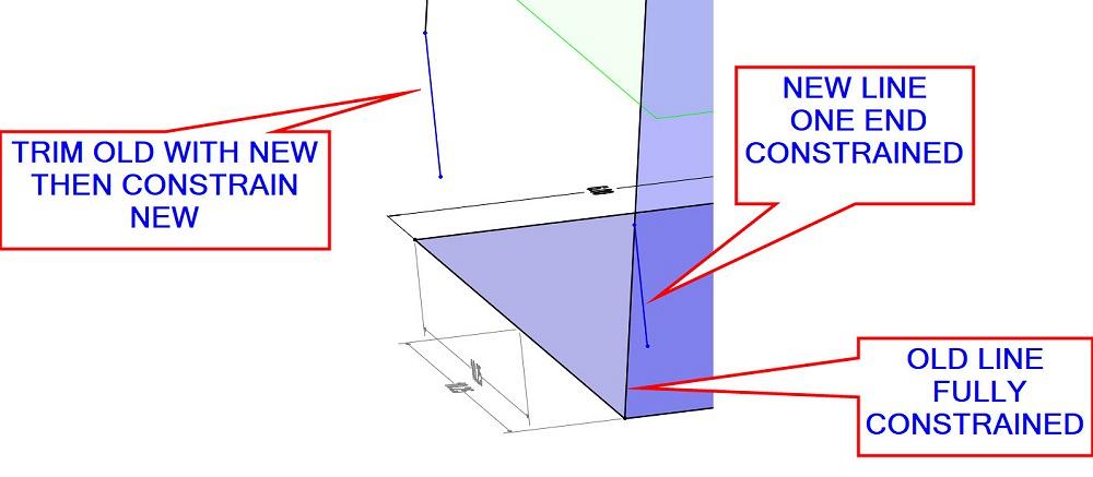
As a CAD tip sidebar, when editing 3D sketch elements that are fully constrained and you wish they were not, Figure 4C shows a trick: Trim away the unwanted constraint. Four new vertical sketch elements have been quickly drawn with only one of their ends coincident to the existing (old corresponding) line.
The trim tool is then used to shorten the sloped line while keeping it aimed at the intersecting corner but not on the corner. As a final flourish in the trick, the new vertical sketch elements are fully constrained between their respective corners and up to the new bottom shelf plane.
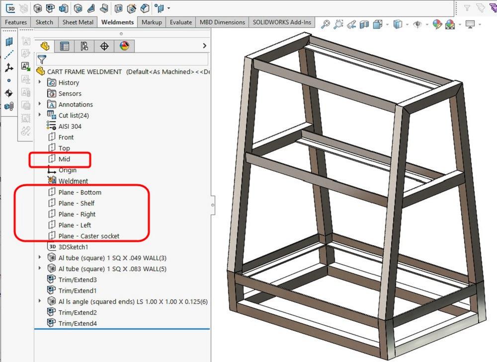
Figure 4D shows the lovely vertical tubes for casters. New support angles have been added for a bottom shelf. This design is slightly past done.
While Figure 1 is essentially our final test fit, Figure 5 shows that 3D sketches and weldments become such entertainment that constraining the CAD jockey might become a priority. Elaboration can become a vice.
And thus, we postpone demonstration of venting and related modeling techniques. Stay tuned.


The Fabricator is North America's leading magazine for the metal forming and fabricating industry. The magazine delivers the news, technical articles, and case histories that enable fabricators to do their jobs more efficiently. The Fabricator has served the industry since 1970.
start your free subscription
Easily access valuable industry resources now with full access to the digital edition of The Fabricator.

Easily access valuable industry resources now with full access to the digital edition of The Welder.

Easily access valuable industry resources now with full access to the digital edition of The Tube and Pipe Journal.

Easily access valuable industry resources now with full access to the digital edition of The Fabricator en Español.
In this episode of The Fabricator Podcast, Caleb Chamberlain, co-founder and CEO of OSH Cut, discusses his company’s...


