- FMA
- The Fabricator
- FABTECH
- Canadian Metalworking
Categories
- Additive Manufacturing
- Aluminum Welding
- Arc Welding
- Assembly and Joining
- Automation and Robotics
- Bending and Forming
- Consumables
- Cutting and Weld Prep
- Electric Vehicles
- En Español
- Finishing
- Hydroforming
- Laser Cutting
- Laser Welding
- Machining
- Manufacturing Software
- Materials Handling
- Metals/Materials
- Oxyfuel Cutting
- Plasma Cutting
- Power Tools
- Punching and Other Holemaking
- Roll Forming
- Safety
- Sawing
- Shearing
- Shop Management
- Testing and Measuring
- Tube and Pipe Fabrication
- Tube and Pipe Production
- Waterjet Cutting
Industry Directory
Webcasts
Podcasts
FAB 40
Advertise
Subscribe
Account Login
Search
Tonnage limits for press brake applications: Absolute or per meter or foot?
Terminology matters when bending metal parts, especially when safety is at stake
- By Steve Benson
- March 22, 2021
- Article
- Bending and Forming
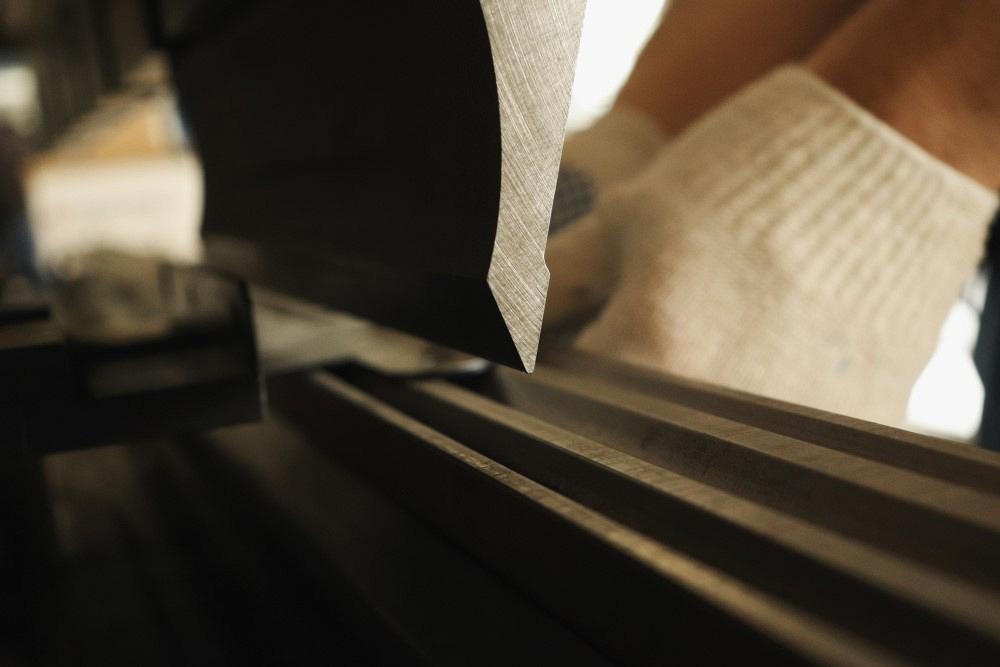
When press brake operators calculate the tonnage limit of a tool, they're finding the absolute tonnage limit. The forming tonnage a specific job requires should be less. Getty Images
Q: I am a mechanical engineer working at a manufacturing firm in India. Press brake tooling is one of our major products, and I regularly refer to your articles for guidance and knowledge.
I was designing a new tool and needed to calculate its strength. The toolset included a very deep gooseneck to accommodate a deep return flange (see Figure 1). I referred to your previous column, “The 4 pillars of press brake tonnage limits,” in which you explain how to estimate tool strength. I’m encountering a discrepancy when I calculate for a gooseneck punch’s full length (3,100 mm) and the tonnage limit per meter (1,000 mm).
I used the punch illustration from that column (see Figure 2) and the associated formula for calculating the punch’s load limits:
P = Punch’s resistance to pressure, in tons per square meter
l = Distance from tool nose to the tangent point between the neck and the inside radius of the tool, in millimeters
T = Width of the tool neck at the tangent point, in millimeters
b = Tool length in millimeters
Z = (b × T2)/6
P1 = (19.98 × Z)/l
P = √ (2 × P1)
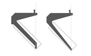
Figure 1. These very deep gooseneck punches, designed to accommodate deep return flanges, exemplify why knowing the required forming tonnage for a job, as well as the tonnage limits of your tools, is so important. The deeper the gooseneck, the weaker the tool becomes.
For the tool I was designing, T was 33.6 mm and l was 295.1 mm. For length (b in the formula), when I calculated the load over the tool’s full length (3,100 mm) as well as per meter (1,000 mm), the results were quite different. When I calculate with 3,100 mm, I get 281 tons, which I divide by 3.1 to get 90.66 per meter. When I use 1,000 mm, I get 150 tons per meter Have I applied these formulas incorrectly?
A: Considering you’re designing a very deep gooseneck punch, I understand why you are concerned about the tonnage required and the total tonnage load of the tool.
To answer your question, the first thing that jumps out at me is the discrepancy in your units of measure. And no, my American readers, I am not talking about the metric system here. I’m referring to the difference between absolute tonnage and tonnage per meter or tonnage per foot.
I will refer you back to the column you cited. In that article, I start with the following statement: “Like many aspects of the sheet metal trade, the terms can be confusing, how they are applied can be confusing, and the worst part, not understanding how tonnage is calculated and applied can lead to some disastrous consequences.”
We all need to be fluent in the terminology. This is especially true when it comes to press brake tooling load limits. Miscalculations can create extreme dangers for the craftsperson, not to mention the added costs of replacing the tool or damage to the press brake itself. Whether you are designing tooling or using the tooling at the press brake, keep safety in mind.
When you push a press brake tool past its tonnage or force limit, bad things will happen. You can bend or destroy the punch, damage the press brake by upsetting the ram (exceeding the centerline load limit), and maybe even destroy the die. Vintage precision-ground tools have been known to throw shrapnel when overloaded. They can explode and sometimes hurl pieces a very long way.
So, what are you calculating, absolute tonnage or tonnage per meter? How do you know what to calculate? That, my friends, all depends on what you need to know. For the tool designer, it is absolute tonnage. For job shop engineering departments or technicians at the press brake, it is the tonnage per meter or foot that matters.
In your case, as a tool designer, you need to calculate the absolute tonnage limit. The equation asks for “length of the tool.” So the answer we can assume is an “absolute tonnage” value and not a “tons per meter” value. You’re not calculating the amount of tonnage per meter a specific job requires (the forming tonnage), but how much tonnage, in absolute terms, your punch can withstand.
When you input a tool length (b in the formula) of 3,100 mm, your result shows an estimate of the absolute tonnage limit your 3,100-mm-long tool can withstand. Similarly, when you input a length of 1,000 mm, your result shows not the tonnage limit per meter, but what your absolute tonnage limit would be if the tool were only 1,000 mm long.
Press brake technicians calculate the tons per inch (or foot or meter) that a specific job requires. They then multiply the result by the bend length to get the job’s forming tonnage, which should never exceed (and, ideally, should be well below) the absolute tonnage limit of the tools and the machine.
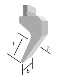
Figure 2. If a punch has no specified tonnage limit from the manufacturer, you can estimate it with a formula that incorporates the dimensions specified by l, b, and T.
Forming tonnage is calculated based on air forming 60,000-PSI-tensile mild cold-rolled steel. When you change the material type, you have a different tensile strength, and you change the force required to make the bend. This means you will have to factor the tonnage load based on the material type.
A 120,000-PSI stainless material is twice as strong as 60,000-PSI mild steel, so you’d need to multiply your result by 2. A 30,000-PSI aluminum is half as strong as 60,000-PSI mild steel, so you’d multiply your forming tonnage result by 0.5. Also know that material strength values vary, which is why tonnage calculations are only estimates. For this reason you should never push your tools or machines close to their tonnage limits. (For specific forming tonnage formulas, you can refer to “The 4 pillars of press brake tonnage.")
These materials and other forming factors illustrate another key concept: The absolute tonnage does not factor in material thickness, tensile strength, or even the die opening—all factors that change the amount of force required to bend (forming tonnage), which, again, cannot exceed the absolute tool pressure rating (or absolute tonnage).
Safety and Forming Methods
You need to consider part length and the gooseneck punch’s profile depth. Note that the formula in your question incorporates the gooseneck profile depth only indirectly. As I noted in my previous column, comprehensive formulas tool designers use get pretty deep into the weeds, incorporating material type, heat treatments, material hardness, yield point coefficients, and other factors. The formula I presented is intended for press brake technicians who use tools that don’t have documented load limits specified by the tool manufacturer. It simply gives a quick estimate of a punch’s ability to withstand a load.
Regardless, in any situation you need to take the time to consider the method of forming and how you intend the punch to be used. Are you coining, bottom bending, or air bending (air forming)? Considering the deep gooseneck profile you’re designing, your only option is probably air bending. Considering the deep gooseneck profile you’re designing, your only option is probably air bending.
Air forming requires the least amount of force to bend the material, and the tonnage requirement is calculated at the point the yield is broken in the material. If you were to try bottoming or coining with your punch profile, odds are you would “spring” the punch (bend it), perhaps even break it. Bottom bending takes five times the tonnage of air forming, while coining can take 10 times as much force. (Note that calculating bottoming and coining pressures are, at best, just educated guesses.)
Die Opening and Tonnage
Because you need to air form, which keeps the forming tonnage low, the die opening becomes an important player. As I am sure you already know, the wider the die opening, the lower the bend’s tonnage requirement. Of course, because you’re air bending, the wider you make your die, the greater the part’s inside bend radius becomes. This changes your bend allowance, setbacks, and bend deduction.
Consider reviewing the print to determine the largest inside bend radius allowed by the print tolerance, then pick your die opening (width) based on the 20% rule. Per this rule, stainless steel forms at about 20% of the die opening (which is where the name comes from), while 60-KSI mild steel—our baseline material—air forms a radius that’s about 16% of the die opening. A 120-KSI material is twice the strength of 60-KSI mild steel, so you’d multiply 16% by 2 and find that your radius will be about 32% of your die opening.
To reduce forming tonnage, use the largest floated radius the customer will allow. Calculate your inside bend radius and bend functions for air forming in the largest possible die opening.
If the customer specifies a tight inside radius, it might be worth your time to discuss with them the possibility of using a larger radius. Using a larger radius will help you make better, more consistent parts while at the same time add life to your tool and press brake.
Use a punch nose radius equal to or just slightly smaller than the naturally floated inside radius of an air-formed bend. If the customer insists on a sharp bend with a small inside bend radius, when you can, avoid using a punch nose radius that’s less than the calculated sharp-bend value—that is, the point at which the bend becomes “sharp.” A bend turns sharp when a narrow punch nose radius forms a crease at the bend, causing it to be far less stable and predictable (For more on this, refer to “How to avoid a sharp bend.”)
For the best results and most consistent bend angles and dimensions in air bending, try using tooling that creates a one-to-one relationship between the floated inside bend radius and the material thickness—a “perfect” bend radius.
Consider a Single-stroke, Two-bend Tool
If you need to form a deep return flange, and you can create a setup with the necessary clearance, you might consider making both bends at once with a single-stroke, two-bend tool that forms both inside flanges simultaneously.
True, the forming tonnage would be more significant, considering you’d be forming two bends with every stroke. But a two-bend tool wouldn’t require the deep gooseneck shape, so you’d likely have a more robust toolset with a higher absolute tonnage limit.
Do the Due Diligence
Challenging parts require a good understanding of the terminology and how to apply it. This includes what to calculate for, such as “absolute” or “per meter.” Whatever route you take—involving a deep gooseneck punch, a two-bend tool, or anything else—you need to perform a tremendous amount of due diligence to make sure that your calculated values are correct.
Precision Press Brake Certificate
For the second time, this is a fully virtual class. Includes 3 sessions of live instruction from Steve Benson, resource materials, and on-demand videos to enhance your learning experience. Live sessions run from Noon to 3 pm CT each day. Plus, receive your own copy of Steve’s textbook, Bending Basics ($95 value). At the end of the course, you’ll have the opportunity to earn FMA’s Precision Press Brake certificate by successfully completing an online exam.
Cost for the 3-day course is $295, or $245 for FMA members.
With more than 30 years experience in the sheet metal industry, Steve Benson is president of ASMA, a supplier of software, textbooks, and training for press brake operators and engineers. He has authored seven press brake texts, programmed related software, and currently publishes the Precision Sheet Metal Chronicle. Steve is an active member of FMA’s Precision Sheet Metal Technology Council.
About the Author

Steve Benson
2952 Doaks Ferry Road N.W.
Salem, OR 97301-4468
503-399-7514
subscribe now

The Fabricator is North America's leading magazine for the metal forming and fabricating industry. The magazine delivers the news, technical articles, and case histories that enable fabricators to do their jobs more efficiently. The Fabricator has served the industry since 1970.
start your free subscription- Stay connected from anywhere

Easily access valuable industry resources now with full access to the digital edition of The Fabricator.

Easily access valuable industry resources now with full access to the digital edition of The Welder.

Easily access valuable industry resources now with full access to the digital edition of The Tube and Pipe Journal.
- Podcasting
- Podcast:
- The Fabricator Podcast
- Published:
- 04/30/2024
- Running Time:
- 53:00
Seth Feldman of Iowa-based Wertzbaugher Services joins The Fabricator Podcast to offer his take as a Gen Zer...
- Industry Events
Pipe and Tube Conference
- May 21 - 22, 2024
- Omaha, NE
World-Class Roll Forming Workshop
- June 5 - 6, 2024
- Louisville, KY
Advanced Laser Application Workshop
- June 25 - 27, 2024
- Novi, MI
Precision Press Brake Certificate Course
- July 31 - August 1, 2024
- Elgin,


