


Executive Vice President
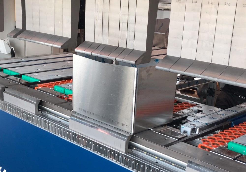
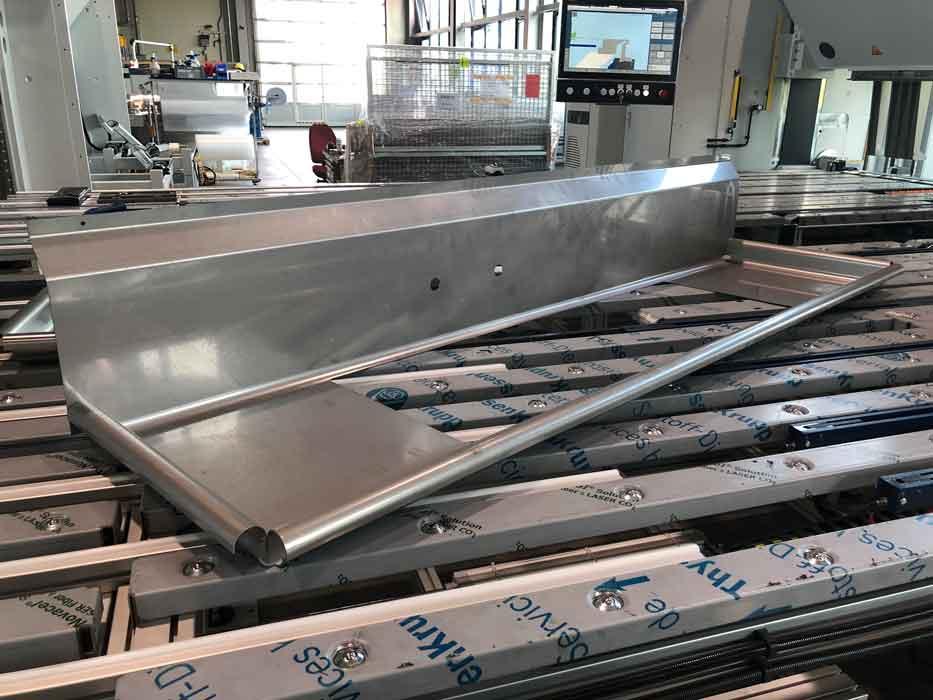
A deep NEMA enclosure is formed on a folder with tall clamping-beam tools safely changed and rearranged by an automatic tool changer.
Industrial folders made their way into the American manufacturing scene in the late 1980s. Early folders were rather slow and unsophisticated but still quickly found their niche. Large piece parts requiring multiple operators on a press brake were easy targets for folding.
A folder’s design incorporates the gauging system into a large ball-transfer table that supports the part during bending. The base of the part stays horizontal, and only the flange is formed to the desired angle. As simplistic as early folding systems were, they became recognized as a way to form accurate parts. And over the years folding has evolved into one of the most accurate, technologically advanced methods of bending available.
Accuracy is one thing, repeatability is another. Any process can be adjusted to hit the target eventually. But the ability to easily and repeatedly hit the target is crucial, especially if parts are destined for processes like robotic arc or laser welding.
After the workpiece is positioned in the folding machine, the upper beam (also called the clamping beam) clamps the material against the lower, or bottom, beam. The folding beam swings in an arc, pivoting the flange on its bend center to the desired angle. If only the outside plane of the material is used to make a bend, thickness variation has little impact on angularity.
This forming method significantly reduces the effects of tensile-strength and grain-direction variation in material. Folded material is stretched in a single direction and around only one side of the tool (see Figure 1). Although this does not eliminate all the effects tensile and grain variation have on angle repeatability, it typically reduces the error and leaves the part well within tolerance.
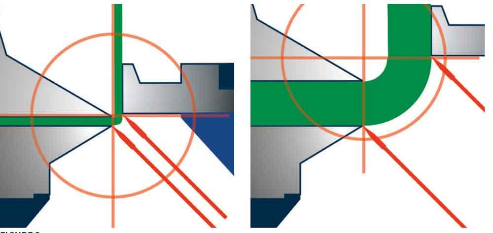
Modern folders have multiple axes that adjust to the proper tool settings for material thickness, type, inside bend radius, and bend angle. As shown in Figure 2, the B axis sets the folding beam’s pivot point to the theoretical center of bend, while the A axis sets the gap between the folding blade and bend center. The A and B axes work together to create the equivalent of an infinitely variable V die, automatically adjusting for material thickness, desired bend radius, and angle. It is through the proper and precise positioning of these two axes that a folder is able to use a single tool set across an entire range of materials (see Figure 3).
The more non-value-added time is spent setting up a part, the less competitive the process becomes. Reducing setup times to a point where they become an insignificant part of the job is a goal everyone should strive to achieve.
A large portion of setup time involves selecting and setting the tools needed. A folder uses tools that are independent of material thickness and type. A machine setup usually involves simply arranging segmented tools to account for different bend lengths and part clearance requirements. Folders have a 1-to-1 ratio between the clamping beam tool height and four-sided box depth. A 15.7-in.- tall tool forms a 15.7-in.-deep four-sided part.
Most modern folders can bend both positive and negative flanges without flipping the workpiece. This simplifies tool setup, eliminating the need to segment bottom tools to accept up-flanges that become down-flanges on a part flip. The rest of the setup is automated by the folder itself.
The folding blade’s position relative to the center of bend sets the inside bend radius. Controlling this gap determines how straight the bend line is and the consistency of the bend radius. A tight radius requires a small gap (analogous to a small V opening) and puts deflective pressures against the folding beam.
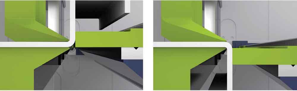
Figure 1
Folded material is formed around one side of the tool. Modern bidirectional folders can form both positive and negative flanges.
To compensate, a crowning system built into the folding beam sets a center crown. During the bending motion, the crown is pressed flat, resulting in a perfectly straight bend line and a consistent radius and bend angle across the bend length. If unable to compensate for the deflection, the gap must be opened to reduce the pressure, resulting in a larger radius. When the gap is properly set, the resulting bend is crisp and straight when set on a flat surface.
Using multiple tools staged across the bed, folders can bend off-center. However, a center-set crown is of little value if the part is fully justified left or right of center. Using the A axis, the folding beam is tilted to rotate the crown to where the part is positioned. Calculating the proper positioning of these axes is enormously complex as it has repercussions on all the axes discussed, including the clamping beam’s position. Such adaptable crowning demands a control system capable of accurately determining the axes’ correct position without operator input.
In fact, modern controllers learn from the folding process in general and can virtually eliminate the need for corrections. This includes calculating a more accurate flat pattern. Axes calculations based on correct data need very little corrective action from an operator.
Repeatable angles are certainly critical to a part’s performance but mean little if flanges are not the proper length. How a part is gauged has enormous implications for accuracy.
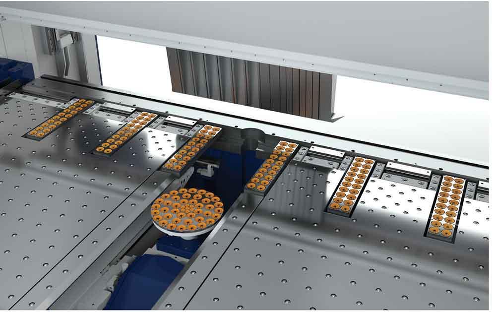
Automated vacuum gauging systems simplify folding while enhancing both repeatability and productivity. A datum point is created by gauging the blank against one of four possible reference points. The gauge moves to position and securely vacuum-grips the part. The part is automatically moved from one bend to the next, never changing its datum reference to the gauge. When the formed side is complete, the vacuum gauge releases the part so the operator can rotate it to the next side to be formed.
Such gauging presents many advantages. For instance, a standard NEMA enclosure has 16 different gauge points that need to be made to complete the part. The vacuum gauge reduces this number to four, minimizing the operator’s influence over part accuracy and the production rate.
This advantage increases as the part gets larger. With folding, part size has no impact on the accuracy of the finished product and very little impact on the processing time. While it certainly takes a little longer to rotate a large, heavy part compared to a small one, the difference is slight. Controlling the bend-to-bend time, the gauging system effectively sustains efficient production rates and part accuracies.
Bump forming of radius profiles (see Figure 4) gains significant advantages with the vacuum gauge as well. A large, perfectly smooth bump-formed radius might have 30 or more individual bends. This is challenging for any operator to do with consistency, especially in large, unwieldy parts. A vacuum gauge feeding the bump forms makes the process no more difficult than making a 90-degree bend.
Thick applications, such as those involving skid steer and earthmoving buckets, use part grippers to clamp the blank. Bump forming the varied radii on these parts lends itself particularly well to folding, with automation often employed for loading and unloading.
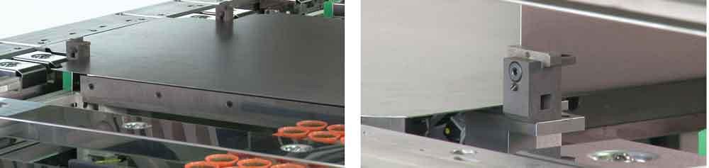
Advanced gauging systems provide up to four different gauge points, each substantively altering where the datum point of reference is on the part. Traditional backgauge fingers reference the part’s overall size and set the datum on the part’s finished, or overall, dimension. The folding beam references the part’s initial flange and sets the datum on the part’s edge forms. Front table stops, or stop dogs, reference to a corner notch or an adjacent flange on the part (see Figure 5).
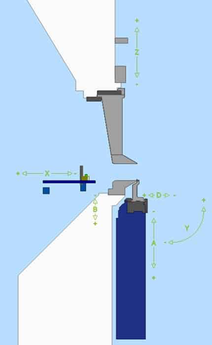
Figure 2
A modern folder has many axes of motion. The A and B axes set the gap between the folding blade and theoretical center of bend.
Pneumatic squaring arms that raise and lower from the gauge table work together with the aforementioned gauge or reference points, creating a multitude of gauging possibilities. Long, narrow profiles can be squared and referenced by a single gauge point. Aligning a part perfectly to the tooling station is another advantage, particularly when a tool gap is needed to accept an intermediate flange.
The pneumatic squaring arms’ most common use is to run two parts simultaneously. The squaring arms act as lateral stops along with a gauge point for reference. As soon as the vacuum gauge table has the blanks, they are formed simultaneously. And while it takes a bit longer to rotate and position two parts, the strategy can nearly double the production rate.
Automatic tool change (ATC) systems have captured the attention of fabricators everywhere, and for good reason. Automating tool setups not only guarantees the proper station size and location, but also allows for parallel processing. While the tool change is taking place, the operator can prepare for the next part run.
An ATC on a folder effectively changes its forming potential. For safe manual changeovers, weight constraints limit the tallest tool to 11.8 in. An ATC allows for heavier, taller tools, including clamping tools 15.75 or even 19.6 in. tall. Clamping beam strokes of 43 in. or greater allow one operator to clear large parts, including tall four-sided boxes.
Some of the latest systems offer fully automated part manipulation. This new concept uses independent left and right vacuum support tables and a center vacuum manipulator (see Figure 6). Instead of the gauge moving within the support table, the entire table moves the part. The center manipulator rotates the part between edge forms, and a hi-res optical system confirms the part is in the correct lateral and radial position. For parts that can’t be run automatically, manual operation is always available. The blanks can be loaded manually or automatically with a vacuum lift or robot.
Automatic part unloading through the front of the folder onto a conveyor is available. During the part unload, the next blank is staged and made ready to fold—a process that minimizes the downtime between part runs.
The Importance of Accuracy
Modern folders produce consistently accurate bends across a range of parts in varying lot sizes. Parts that fit poorly create unnecessary burdens in assembly, with robotic welding or laser welding particularly susceptible to poor part quality. Even a skilled operator can overcome only so much for so long before the process begins to degrade and suffer.
Folders have evolved dramatically since their American debut in the 1980s. They have become sophisticated systems for forming jobs that demand high accuracy, repeatability, and productivity—three requirements likely to become even more important in the years to come.


The Fabricator is North America's leading magazine for the metal forming and fabricating industry. The magazine delivers the news, technical articles, and case histories that enable fabricators to do their jobs more efficiently. The Fabricator has served the industry since 1970.
start your free subscription
Easily access valuable industry resources now with full access to the digital edition of The Fabricator.

Easily access valuable industry resources now with full access to the digital edition of The Welder.

Easily access valuable industry resources now with full access to the digital edition of The Tube and Pipe Journal.

Easily access valuable industry resources now with full access to the digital edition of The Fabricator en Español.
Seth Feldman of Iowa-based Wertzbaugher Services joins The Fabricator Podcast to offer his take as a Gen Zer...


