


Professor of the Chair of the Institut für Umformtechnik und Leichtbau (IUL)
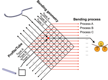
Figure 1: The bending process matrix uses bending geometry and raw material shape (profile or tube) to determine the most appropriate process.
The number of industrial applications for tubular and profile components is unlimited. For example, reducing automobile weights requires lightweight structures paired with high stiffness. For this application, tubes and profiles with closed cross-sections are especially suitable. Furthermore, with the help of a variety of bending processes, various lots of bent components can be produced cost-effectively. The electric automobile is a prime, current example. Altered auto bodies require flexible production concepts for low-volume production. This flexibility allows new products to be brought to market efficiently right from the start. This is a necessary first step for establishing the electric car as a viable consumer product.
Because of all the advantages of the use of bent components, manufacturers of bending machines and their users are facing steadily growing customer requirements regarding the geometry of bent components. While technological restrictions remain, bending radii are decreasing, 3-D geometries are becoming more complex, and tolerances regarding surface contours and connection faces are getting tighter. Regrettably, as part complexity increases, the scrap rate also increases. Moreover, with the existing variety of bending processes, material-specific restrictions can be exploited to a greater or lesser extent. Knowledge of the processes and their efficiencies is critical, ultimately determining whether a planned product will bring in profits or losses in subsequent production. Meanwhile, knowledge of the bending process is based on the level of education and the experience of the machine operator and the machine manufacturer.
For designers of bent components, bending process selection can be highly confusing and unsatisfactory. In many cases, a single geometry can be bent successfully by many of the available bending processes, so the best choice isn’t clear. Common criteria for the assessment of complex geometries do not exist.
Funded by Germany’s Federal Ministry of Economics and Technology (Bundesministerium für Wirtschaft und Technologie, or BMWi), the research project “RoPro” of the Chair of Forming Technology at University of Siegen (Siegen, Germany), the Institute of Forming Technology and Lightweight Construction (IUL) at TU Dortmund University (Dortmund, Germany), and bending machine manufacturer Tracto-Technik GmbH & Co. KG (Lennestadt, Germany) aims to reduce the difficulties in choosing component-specific bending processes. For the project, extensive searches of current standards and guidelines have been carried out, as were analyses of proprietary company guidelines. These and other results from the project will be incorporated (anonymously) into a standardization application to the Fundamental Technical Standards Committee of the DIN (German Institute for Standardization). The aim is to obtain a German or an international standardization that establishes standards in the field of profile and tube bending technology.
As a result of the project, designers of bent components receive a tool that suggests an effective and economic bending process based on bending geometry and semifinished product. A bending process is considered effective if it achieves the necessary bent shape and conforms to the specified tolerances. The economic-efficiency analysis is based on individual investment costs of the bending processes, which are included in the tool.
The core idea of the research project is the development of a matrix (see Figure 1) that helps to identify the most suitable bending process based on a preselection of bending geometry and semifinished product (material and cross-section) to be used. Thus, the creation of interfaces between semifinished product, bending geometry, and bending process is necessary. During the project, the existing standards were collected and evaluated to categorize semifinished products by their bending-specific parameters. Next was the evaluation of typical bending geometries, which were likewise sorted into different quality categories.
An important secondary criteria is bend quality, which was defined independently from the production process. The quality of the bent workpieces was based on the quality of the incoming material (before the bending process). For this validation, knowledge from the universities and a variety of fabricators was used.
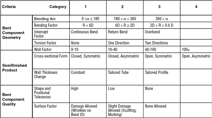
A bending component is defined by nine criteria (see Figure 2). The first four criteria describe the geometry of the bent part. The tube or profile is defined by criteria such as the wall factor, the cross-section, and the wall thickness deviation.
The criteria shape and positional tolerances and surface factor define the complexity of the workpiece. Bent components can be sorted in four categories with a rising complexity in manufacturing progress.
The geometry of the bent component is critical for the choice of a bending process. The dimensions of the part have to be adaptable for the bending machine size. The geometry of the components can be described by various criteria: bend angle, bend factor, intercept factor, and torsion factor.
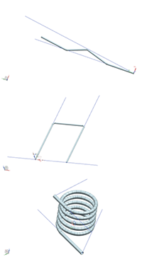
Figure 3: The intercept factor describes the bending direction and the positions of the bent sections toward each other. Rays in the Cartesian coordinate system that are nearly parallel predict no problem. As the bend severity increases, the possibility of trapping the die in the component increases.
Bend Angle. The first criterion is the bending angle of the bending arc, which has three possible categories. Category 1 is from 0 to 180 degrees; this range can be achieved by most processes and machines. Category 2 is from 180 to 360 degrees, and Category 3 is any angle greater than 360 degrees. To produce bent parts categories 2 and 3, additional tools or machine measurements are necessary. Furthermore, the kinematics of the machine, the clearance, and the free space must be taken into account to prevent a machine crash.
Bend Factor. The maximum strain the material experiences through the bending process is considered by the bending factor. The bending factor B is defined as the quotient of the average bending radius R and the outer diameter H (B = R / H). In the U.S., this is commonly called D.
The technical limit of the bending factor is determined by the profile material and the profile cross-section. A minimum bending factor of B = 0.5 can be achieved geometrically. The bending factor is subdivided in three categories.
Intercept Factor. The newly defined intercept factor (see Figure 3) describes the complexity of the bending geometry. Rays start from the ends of a component. These rays surround the limits of 2-D bent parts in one plane of the Cartesian coordinate system. The difference in angle between two rays predicts the bending difficulty. An extreme case is called overbending (see Figure 4).
Category 1 of the intercept factor includes bent parts with bends in multiple directions. The bending angles are small. There are neither undercuts nor return bends. Typical examples are S-shaped bent components or fitting tubes for automobile dashboards. As the angle between the limiting rays increases, the risk of overbending increases. Therefore, it is necessary to check the bending contour for the proposed bending method.
Category 2 includes geometries with a rearward profile. This usually includes open complex contours. The freedom of movement of the bending machine must be tested before the start of the bending procedure.
Category 3 includes several cross bends. The contours can be produced only with difficulty and always require careful investigation before bending. Furthermore, Category 3 is assigned in cases of rearward bending and multiplane (complex) bending.
Torsion Factor. To counteract torsion during the bending process, it might be necessary to change the design of the bent part or to provide a moment that counteracts the torsion. In contrast to inadvertent torsion, some bent parts need torsion applied in a specific area. For this purpose and for describing inadvertent torsion, the torsion factor criterion is suitable. According to Figure 5, this parameter describes the existence of torsion and its direction around the longitudinal axis of the bent part. The torsion factor has to be considered particularly with open profiles, because these parts generally have a very low moment of resistance against torsion.
At torsion factor 1, torsion is non- existent. Torsion factor 2 describes plastic torsion in one direction around the longitudinal axis of the bent part, whereas torsion factor 3 implies torsion in both circumferential directions.
Dimensions. The part’s dimensions have a significant influence on selecting an appropriate bending process. The dimensional factors are the cross-sectional shape and the ratio between wall thickness and outside diameter. As these factors become increasingly severe, constraining the tube is necessary to prevent a decrease in quality.
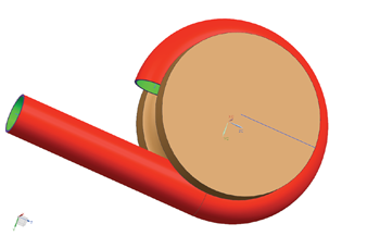
Figure 4: A bending geometry that traps the bend die in the bent part is a phenomenon known as overbending.
Wall Factor. Where tubes are concerned, the wall factor (W = H / s) describes the quotient between the tube’s outside diameter (H) and the wall thickness (s). Reflecting the common process limitations, the wall factor is classified into four categories.
Cross Section. The continuous development of tube and profile bending processes has led to increasing use of open, asymmetric, and varying cross-sections, so the specific shape is an increasingly critical factor when selecting an eligible bending process. For this reason the criterion cross-sectional form has been introduced, which is decisive in selecting a bending method and the respective bending tools. The criterion itself is subdivided into closed and open profiles and for both in symmetric and asymmetric cross-sectional forms.
Wall Thickness Change. To meet the increased requirements for lightweight construction there will also be a rising demand for bent parts with a varying wall thickness distribution. This fact is recognized by the additional introduction of the wall thickness change criterion. A distinction is made between bent parts with constant wall thickness; bent parts with varying wall thickness along the longitudinal axis, also known as tailored tubes; and bent profiles with varying wall thickness along the longitudinal axis, or tailored profiles.
The term tailored implies the development of parts with wall thickness adapted to the expected operational loading conditions to save material and weight. In the simplest case, tailored tubes, only the inside diameter (ID) of the tube differs along the longitudinal axis, so that just the inside tooling has to be modified. The key issue is the changing clearance between the tube’s ID and the mandrel’s OD, which prevents the tube from collapsing. Much more complex is the bending of tailored profiles, which requires special adaptations of all bending tools.
Shape and Positional Tolerances. The competitive pressure of the global market is driving the increasing quality of finished bent parts. Special quality criteria ensure that the tendency toward constant increase of customer expectations and quality requirements is taken into account when selecting a specific bending process. The criterion shape and positional tolerances defines the permissible deviation of the bent part compared with its reference geometry. Category 1 allows considerable deviations that are within the scope of most bending machines. Category 2 supposes closer tolerances, and Category 3 describes high dimensional accuracies with adherence to very close tolerances. This category therefore requires a thorough evaluation of the eligible bending method(s), as well as selection of semifinished parts to meet the highest demands for tight dimensional tolerances. After bending, Category 3 products often need calibration in a hydroforming press.
Surface Factor. High-quality surfaces are crucially important in cases when the part is visible in the final assembly. The surface factor criterion describes allowable damages or deviations of the bent part’s surface. The surface factor also is classified in three categories: allowable deviations from the reference surface quality (deep scratches and grooves, as well as geometrical deviations at the inside curve), minor deviations without any technical or functional losses, and a flawless surface.
The criteria for categorizing the bending performances provide clear descriptions of bent parts in regard to production complexity. Based on these criteria, it is possible to select an optimum bending method for a certain bent part, taking into account the bent part’s geometry and the manufacturing limitations of the bending method.
The project staff continues to develop and refine bending criteria and welcomes suggestions and criteria validation by tube fabricators.
When the research results of this project are transferred into a national or international standardization process, the criteria should become industry standards. Overall acceptance of the standards is the prerequisite and can be used for increasing the application possibilities of tube and profile bent parts. Future work will include categorizing the various bending processes, their variations, and tool setups. A detailed catalog that includes the performance of each process is underway.
The authors gratefully acknowledge financial support provided by the German Federal Ministry of Economics and Technology, which was based on a decision by the German Federal Parliament.
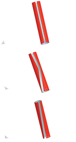
Figure 5: The torsion factor describes the component’s geometry with regard to deformation due to torsion. Possibilities are no torsion (torsion factor 1, top), torsion in one direction (torsion factor 2, middle), or torsion in two directions (torsion factor 3, bottom).


The Tube and Pipe Journal became the first magazine dedicated to serving the metal tube and pipe industry in 1990. Today, it remains the only North American publication devoted to this industry, and it has become the most trusted source of information for tube and pipe professionals.
start your free subscription
Easily access valuable industry resources now with full access to the digital edition of The Fabricator.

Easily access valuable industry resources now with full access to the digital edition of The Welder.

Easily access valuable industry resources now with full access to the digital edition of The Tube and Pipe Journal.

Easily access valuable industry resources now with full access to the digital edition of The Fabricator en Español.
In this episode of The Fabricator Podcast, Caleb Chamberlain, co-founder and CEO of OSH Cut, discusses his company’s...


