


Director of Sales
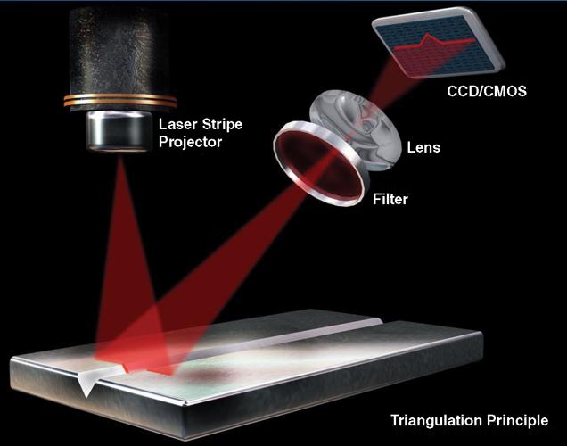
Figure 1
The main components of a laser vision system are the laser source and the sensor, which is either a charge-coupled device (CCD) or a complementary metal-oxide semiconductor (CMOS). The lens provides the ability to focus the laser light, and the filter eliminates unwanted wavelengths.
Editor’s note: This article is based on “Laser Vision and Digital Controls Aid Both Pipe Mill and Pipe Line Welding,” presented by Stephen Thacker, general manager, St-Laurent, Quebec, Canada, at the Tube & Pipe Association International®’s 2013 Tube Producing Conference, New Orleans, La.
Laser vision systems and advanced digital controls are no longer just for seam tracking on pipe mills. These days they are used to improve pipe quality and mill productivity. Manufacturers are increasingly demanding the use of such systems to remove human influences on quality and to capture and retain relevant production data.
Both longitudinal and spiral submerged arc welding (SAW) pipe mills can be equipped with laser vision and control systems for such functions as bevel measurement, weld seam tracking, weld bead inspection, and mill control.
Laser vision is based on the principle of triangulation, a method of extracting geometric information from a series of measurements (see Figure 1). This type of system uses a structured light source, usually a laser diode, in conjunction with an imaging device to produce a series of 3-D images that allow the manufacturer to get a good sense of the weld joint’s characteristics.
The main advantage of triangulation is that it provides dimensional information only. This means that it is not influenced by surface variations, such as color changes or surface markings, and that ambient light has no influence on the imaging process. In practice, these factors can disturb the process, but special measures and proper filters nullify their effect.
A laser stripe system consists of a laser emitter that projects a stripe of light across the weld joint; the stripe is deformed by the shape of the weld joint. A linear detector intercepts the laser light and interprets the deformations as distances, creating an image of the weld joint profile.
Lasers have proven themselves useful at several stages of the pipemaking process.
Beveled Edges. Proper beveling is the first step in making a good weld, but setting up the beveler properly isn’t enough. Monitoring the edges helps to track beveling problems.
The laser vision system can measure quite a number of critical bevel characteristics in real time as the strip passes the sensors: ID and OD bevel angles and heights, the root face angle and height, the strip thickness, and whether the strip is centered in the mill.
Seam Tracking. Both longitudinal and spiral pipe mills make extensive use of laser vision systems for weld tracking. Laser tracking enables high-speed welding with accurate wire positioning, which reduces defects. In fact, given that the laser sensor measures joint characteristics such as shoulder and root gap, the welding process can be controlled adaptively. For example, as the joint varies in width, the system can adjust the wire feed speed, travel speed, voltage, or current to compensate.
Figure 2
In addition to tracking the bead, the laser system can provide additional data, measuring bead width and height, mismatch, toe angles, and defects such as undercut or gross porosity.
UT Guidance. Using a laser vision system to guide an ultrasonic test (UT) probe along the weld bead helps to ensure the probe stays centered on the bead. The laser sensor measures the bead width and height and calculates a tracking point on top of the bead profile (see Figure 2). That tracking point is used by a motion system or slide upon which the UT probe is mounted.
Coating Control. The pipe-coating process uses vast quantities of expensive consumables. By using the laser sensor to detect the weld bead as the pipe is rotated and coated, the system can control the outer layer thickness accurately over the bead and over the rest of the OD.
The ability to distinguish between the weld bead and the rest of the circumference is critical to maximizing this process’s efficiency. This is because manufacturing standards dictate a minimum coating thickness and, because the sprayer usually is mounted at a fixed distance from the pipe, a little less coating adheres to the weld bead than to the rest of the pipe. To compensate, the operator sets the coating stations to apply a little more coating than necessary everywhere so that the relatively thin coat over the weld bead is thick enough to comply with the manufacturing standard.
The laser sensor control allows two solutions: Apply less coating or change the spray head angle slightly.
Process Control. The number of spiral pipe mills in use throughout the world increased dramatically in the first decade of the 2000s and continues to grow. Part of this expansion is driven by the acceptance of spirally welded pipe for oil and gas transmission. This application in particular imposes stringent standards on pipe quality and on manufacturing processes. Fortunately, new technology is available to improve the processes and to help achieve the standards.
This new technology is largely digital in nature. It includes industrial networking, digital SAW power sources, sophisticated digital sensors, and advanced digital control systems. These can be combined into a single integrated mill control system.
New digital welding power sources enable a wider range of weld procedures, while at the same time being easier to use. This makes it possible to increase efficiency in various ways, while at the same time facilitating accurate parameter control and data reporting.
Laser vision sensors are used to achieve performance gains in several areas—validating weld bevels, measuring and controlling gaps and mismatch, and inspecting weld bead profiles.
Laser vision also helps to improve dimensional control. For example, real-time joint gap measurements can be used for automatic gap control on the mill. The laser sensor sits in front of the torch and measures and calculates five key joint geometry features: shoulder width; shoulder high and low points; root high and low points; root gap; and joint area.
Previously the sensing, welding, and control systems were distinct from each other. For example, control of the ID and OD weld heads often was carried out at independent subsystems. Digital spiral mill control systems combine mill control and weld control into a single networked control system. Mill operation is easier through better operator interfaces, improving troubleshooting and maintenance by putting all of the sensors and controls on a single network.
The central part of the control system is a pair of networked PLCs. One PLC controls the mill feed section, including coil loading, edge milling, and main drives. The second PLC controls the forming and payoff section, including the weld controls and laser seam tracking systems.
The human interfaces consist of a main control console, a pair of consoles for the ID and OD operators, and the usual collection of local operator stations at work points along the mill. An integrated network also allows supervisory control and data acquisition (SCADA).
In most cases, a laser vision system helps to improve a process by taking precise measurements and feeding this information back to the control system. In others, this type of system helps to resolve a difficult and expensive problem. One specific example involved a pipe manufacturer that found ID weld defects after the pipe had gone through several additional weld stations for the fill and cap passes. To solve this problem, the manufacturer installed a 3-D laser sensor on the ID weld station and integrated the inspection results with images taken by a conventional 2-D camera. The unit was mounted to a carriage that provided 360 degrees of travel, providing a complete root pass inspection.


The Tube and Pipe Journal became the first magazine dedicated to serving the metal tube and pipe industry in 1990. Today, it remains the only North American publication devoted to this industry, and it has become the most trusted source of information for tube and pipe professionals.
start your free subscription
Easily access valuable industry resources now with full access to the digital edition of The Fabricator.

Easily access valuable industry resources now with full access to the digital edition of The Welder.

Easily access valuable industry resources now with full access to the digital edition of The Tube and Pipe Journal.

Easily access valuable industry resources now with full access to the digital edition of The Fabricator en Español.
In this episode of The Fabricator Podcast, Caleb Chamberlain, co-founder and CEO of OSH Cut, discusses his company’s...


