


Contributing Writer
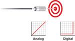
Figure 1 Figure 1
Measuring important part features using analog sensors during the stamping process can reduce the need for time-consuming in-process checks, expensive attribute gages, and costly part-sorting at the press.
A die protection program that prevents mis-hits and die crashes and prevents unplanned downtime also can save a stamping company a significant amount of money. Sensors used to detect short or long material feeds, parts ejecting from the die, pierced slugs properly falling out of the shoe, and cams returning to home position all work together to detect anomalies in an otherwise controlled and repeatable process.
A well-designed die protection system, with sensors properly mounted and connectivity protected from damage, can monitor critical events in the die effectively for many years with little maintenance. However, while monitoring static events during production to prevent die damage and increase press speeds is an extremely important method of errorproofing, there are other reasons to automate the stamping process. Maintaining part quality through the use of sensors and control systems can ensure that parts with out-of-tolerance conditions are identified and contained before they have the chance to get to the customer's good-parts bin. This often is accomplished using analog output sensors. Analog sensors work well in part measurement applications, because instead of just indicating presence of the part, They can check a part feature for quality and "measure" it by indication of how close it is.
The difference between analog sensors used in part measurement and digital sensors used for die protection is the output of the sensor. Digital sensors detect the presence of a target. If the target is within the operating range of the sensor, it switches, providing a discrete, binary on or off output in the form of either 0 or 24 volts. In contrast, an analog sensor provides an output range, often measured in voltage (0 to 10 volts) or current (4 to 20 mA). Analog sensors' output depends on the distance the target is located from the sensor. As the target moves closer to the sensor, the output increases (Figure 1).
For a part that contains a right-angle (90-degree) bend, the part print may call out a tolerance of +/- 2 degrees. Even though at setup and initial inspection the part is acceptable, the tool may begin to wear or fatigue; the material thickness may change slightly from coil to coil, or even become softer; or the ram of an older press might back off. All these things can allow the 90-degree bend to relax, causing a quality problem.
An analog inductive proximity sensor can monitor any area on the part below the bend line (Figure 2). If the angle becomes too shallow or deep, the press controller will indicate the part is out of tolerance according to the output from the sensor. Depending on the technology installed in the press controller or PLC, the press can be stopped; the part can be diverted to a scrap bin after it exits the die; or by using movable sections, the form blocks can open or close to tighten or loosen the form as necessary. All of this can occur while the press is running continuously (Figure 3).
There are a few things to consider, of course: The measurement must occur after the work is completed, but while the part is still held in place by a stripper or pressure pad. This prevents nuisance faults or false readings caused by movement of the part or misalignment after the bottom of stroke.
The sensor is not the only part of the technology equation. Interfacing with the press controller is a consideration as well. Many modern controllers have analog inputs and can process voltage or current outputs. To prevent the need to retrofit or upgrade older controllers, stampers can easily integrate setpoint controllers with analog inputs and digital outputs. Connecting the output of the analog sensor and "dialing in" setpoints (such as high and low tolerances), allows a digital output to be sent to the press controller when one of those setpoints is breached. (This operation is similar to a thermostat's – points are set for cold and warm. When the room gets too cold, the furnace turns on to bring the room temperature back into an acceptable limit. When the room is too warm, the air conditioner turns on to cool the room off.)
With a digital setpoint controller, one trigger point can be set to the low depth of a draw, and another can be set to the high end of the tolerance. As long as the depth stays within those parameters, the press will continue to run. For applications such as this, test shields often are necessary to perform setup (Figure 4). These test shields are made of acceptable parts—one just outside the low tolerance, and the other barely outside the high tolerance. Using this process, stampers can be sure that when the tool is set up, the dimensional measurement is accurate—a requirement often dictated by a company's quality system. It still is a good practice to check with an analog sensor to verify correct angle.
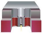
A can with a draw depth of 1.000 in. has to be held to within 0.005-in. tolerance. After the final draw in an idle station, an inductive proximity sensor with analog output (Figure 5) mounted directly under the pressure pad is aimed at the bottom surface of the can. At the bottom of the stroke, the sensor sends an output based on the distance between the bottom of the draw and the sensor face. The press controller can be programmed to stop the press if the dimension is either shallow or deep.
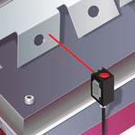
Figure 2 Analog sensor installed in progressive die errorproofs bend angle.
If the measurement is low, a number of problems could be present: The draw actually could be shallow; a foreign object between the strip carrier and the die could be standing the part off; the shut height could be set too high; or the draw punch could be damaged. Depending on the technology available at the press, the draw depth could be sampled for a number of press strokes to determine if the condition continues or if an anomaly has occurred during a single hit. With a PLC with a shift register and counter in the logic, the single bad part can be diverted into a scrap bin after it leaves the die, and the number of bad parts can be counted during production.
Necessary measurements can occur outside of the die, or on the press as part of setup. Many older presses are not equipped with methods of measuring the ram shut height. Clumsy or inaccurate methods of measurement, such as using feeler gauges or "dry hitting" the press with lead, often create setup problems, because they cannot determine if the ram is too low – only that it's too high. A linear transducer with analog outputs and a digital display can simplify repeatable shut height setups (Figure 6).
When a shut height adjustment needs to be made, the display shows the current height in real time, and if the ram begins to back off because of excessive tonnage or capacity, the transducer display shows the difference.
Airflow sensors can aid in setup as well, both by monitoring pressure in a nitrogen manifold and indicating pressure in the counterbalance cylinder on the press.
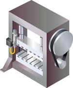
As the material uncoils and advances into the feeder, there is a risk of "straight-lining" the coil if it is not released from the spool fast enough. A long-range analog laser sensor with discrete digital outputs can be used to monitor the loop of material as it uncoils. When the material gets too high, an output from the sensor can be used to activate the uncoiler to release material into the feedline.
As more slack is created, the risk of pulling the material back out of the feeder, and subsequently out of location in the die, is greatly reduced. Another output from the same sensor can stop the uncoiler to prevent material from hitting the pressroom floor. This maintains the delicate balance between too much and not enough slack moving into the feeder (Figure 7). Applications such as these can help minimize the nuisances created by a less-than-perfect setup.
These are just a few applications in which using analog sensors can help increase productivity in the pressroom. Because errorproofing the metal forming process is more than detecting whether a part fell out of the die after the bottom of the stroke, or all of the cam-pierce slides have returned home, automating quality checks and fast, repeatable setups using analog sensor technology can help overcome problems that cost valuable time and money.


The Fabricator is North America's leading magazine for the metal forming and fabricating industry. The magazine delivers the news, technical articles, and case histories that enable fabricators to do their jobs more efficiently. The Fabricator has served the industry since 1970.
start your free subscription
Easily access valuable industry resources now with full access to the digital edition of The Fabricator.

Easily access valuable industry resources now with full access to the digital edition of The Welder.

Easily access valuable industry resources now with full access to the digital edition of The Tube and Pipe Journal.

Easily access valuable industry resources now with full access to the digital edition of The Fabricator en Español.
In this episode of The Fabricator Podcast, Caleb Chamberlain, co-founder and CEO of OSH Cut, discusses his company’s...


