


Stamping 101: Anatomy of a Mechanical Stamping Press
Stamping press functions
Editor's Note: STAMPING Journal® will explore hydraulic press capabilities, the differences between mechanical presses and hydraulic presses, as well as servo and pneumatic presses in "How to select a press," which will be published in the March issue.
Understanding the fundamentals of press technology requires, at minimum, that you be able to answer some basic questions:
- What is stamping, and what does a stamping press do?
- What materials are stamped most commonly?
- What is a die or press tool, and how is it used?
- What are the main types of stamping presses?
- What are mechanical press drives, and how do they work?
Before you can examine the structure of a press, you must take a step back and look at a stamping press's function.
Stamped components are made by forming, drawing, trimming, blanking, or piercing metal—in sheet or coil form—between two halves (upper and lower) of a press tool, called a die (see "Stamping 101: Die basics," page 22). The upper member is attached to a slide, and the lower member is clamped or bolted to the bed or bolster. The die is designed to create the shape and size of a component, repeatedly, and in quantities that will meet production demands. The two halves of the die are brought together in the press. Both force (load) and accuracy are required to achieve the repeatability and tolerance demands for the final stamped and assembled part.
Stampings are manufactured from many different materials. For example, beverage cans are formed from aluminum; many automotive parts are stamped from high-strength steels; doorknobs and lock mechanisms are stamped from brass. Structural parts, such as nail plates and joist hangers, are stamped from galvanized steel.
Sizing the Die to the Stamping Press
To size a die to a press, two calculations need to be performed. The first is tonnage (force) and the second is energy consumed. Every press in the world is rated by the tonnage (force in tons) that it can apply from bottom dead center (BDC) of the press cycle to BDC of the same press cycle.
The tonnage rating of a press must not be confused with the energy generated by the flywheel of a press. Each press has a tabulated graph of energy supplied by the press manufacturer—and each one is different. This is because flywheel-generated energy is dependent on the size of the flywheel and drive ratio. This also makes a big difference in the cost of a press.
Due diligence is needed when sizing a die. Many engineers who are very experienced in die design or in production or in press procurement but who are not experienced in all fields fall into the trap of considering only one of the two calculations. This question is then asked too late in the day: "Why can we not run this part?"
Stamping Press Drives and Frames
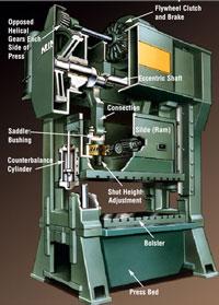
Presses fall into four main categories—mechanical (seeimage at top of page), hydraulic, servo, and pneumatic. Each category derives its name from the drive source that generates the pressure (force) on the die to form the finished stamping. Each category can be further divided into one of two different frame designs: straight-side or C-frame. Each type of press can have single- or double-slide (ram) connections. A low-tonnage press can have a single- or double-ram connection depending on whether the accuracy required justifies the additional cost of a double-ram connection.
Straight-side presses have two sides and four to eight guideways for the slide. This reduces the deflection and enables them to handle off-center loads better.
Figure 1. In a nongeared drive, the flywheel, clutch, and brake are located on the eccentric or crankshaft. As a rule of thumb, full press energy is available between half of the top press speed and the top press speed.
C-frame presses are shaped like the letter C or G, and most are manually operated. Because of its open form, a C-frame press is subject to higher deflection under off-center loads than a straight-side press. The slide is guided by two V-guides or box guides.
Other types of presses, such as transfer, hydroform, hot forge, and friction screw, are built for special applications.
Mechanical Press Drive Transmissions
Mechanical presses also can be categorized by the type of drive transmission that exerts force on the die: flywheel, single-geared, double-geared, double-action, link (also called alternative slide motion [ASM]), and eccentric-geared.
All are powered by an electric motor that drives a large flywheel. The flywheel stores kinetic energy, which is released through various drive types. For each 360-degree cycle of the press, or stroke, energy in the flywheel is consumed as the part is made in the die. This causes the flywheel to slow, usually between 10 and 15 percent. The electric motor then restores this lost energy back into the flywheel on the upstroke of the press. The press is then ready for the next cycle.
If the percentage that the flywheel slows (slowdown), determined in strokes per minute (SPM), is greater than 15 percent, the electric motor will not have enough time to restore this lost energy, and the press will slow down too much. After several strokes, the press will jam on BDC. This occurs when the die tonnage or energy has been calculated incorrectly.
To stop and start the press, you use an electronic control to a clutch and brake, which in turn disengages the flywheel to the press drive. Most clutches and brakes are spring-applied and have either pneumatic or hydraulic releases. The stopping time of the clutch and brake is critical in determining both the speed that the press can be run and the safety of the operator and die.
Flywheel-drive Mechanical Press. Presses with flywheel drives (see Figure 1) are used for piercing, blanking, bending, and very shallow drawing with progressive dies. The normal press tonnage is between 30 and 600 tons. They run at high speeds—125 to 250 SPM on the low end, to speeds in excess of 1,000 SPM on the high end. Press stroke length is always kept as short as possible, as this affects press speed. The average stroke is 2 inches. If more energy is required at the lower speeds, an auxiliary flywheel can be added to the drive. However, the energy will never reach that of a geared press.
A flywheel-driven press normally is rated at full tonnage at 0.062 in. from BDC of the press cycle to BDC of the same press cycle. The flywheel, clutch, and brake are located on the eccentric or crankshaft. As a rule of thumb, full press energy is available between half of the top press speed and the top press speed. However, it is best to check with the press manufacturer for confirmation.
You need to check die calculations carefully when the material is thicker than the press-rated capacity. You must become aware of what to do with high snap-through (reverse loads) and press vibration when using ultrahigh speeds.
Flywheel presses are designed with dynamic balancing of the upper die and press slide (ram) weight using an opposing force. Without this opposing force, the press would walk around the floor at high speeds.
Figure 2. This is the most popular press drive used by contract stampers in the automotive industry. It can be run at continuous speeds down to 28 SPM, although typical press speed range is 40 to 80 SPM.
Single-geared Mechanical Press. This is the most popular press drive used by contract stampers in the automotive industry (see Figure 2). The tonnage ranges from 200 to 1,600, with a two-point connection to the slide. The gear ratio allows the flywheel to run fast, maintaining energy, while the press speed is much slower than a flywheel machine. Single-geared presses normally are rated at full tonnage between 0.250 and 0.500 in. from BDC to BDC. The correct rating to choose for your application depends on the die's energy requirement. This rating will make a difference in press price and drive size.
A single-geared press is used for progressive stamping with dies having shallow draw or forms with piercing and blanking. This type of press drive transmission can be run at continuous speeds down to 28 SPM. A typical press speed range is 40 to 80 SPM with a 12-in. stroke. Remember the rule of thumb regarding energy—full press energy is available between half of the top press speed and the top press speed.
Always look for a press with a twin-end drive that has opposing helical gears with an eccentric shaft. This will improve accuracy, reduce deflection, and increase longevity.
The single-geared drive can be fitted with an alternative slide motion (ASM), or link drive.
Double-geared Mechanical Press. This press is used when a continuous production speed of lower than 28 SPM is needed (see Figure 3). It is good for heavy-duty applications, especially for stamping high-strength steels. The drive gear ratio allows the flywheel to maintain its speed while the press runs slower than both the flywheel and single-geared press. Depending on flywheel size, very high energy can be generated with this type of drive. Press tonnage is from 200 to 1,600, with a two-point connection to the slide.
A double-geared press drive is good for transfer die work. Transfers typically run at 15 to 30 SPM. Presses with this drive normally are rated 0.500 in. from BDC to BDC. Some presses have a special drive rated at 1 in. from BDC to BDC; it is used for drawing, forming, blanking, and piercing with transfer and progressive dies.
The drive can be fitted with an alternative slide motion, or link drive.
Link Drive, or Alternative Slide Motion. This option allows reduced slide velocity during the working portion of the press cycle. It also may allow up to a 25 percent increase in production (see Figure 4).
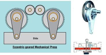
Eccentric-geared Mechanical Press. This type of press and drive is used where a very long stroke is required — normally in excess of 24 in. (see Figure 5). All of the features of a double-geared press apply to this drive design; however, accuracy is not as good as an eccentric-shaft press because of the clearance with the arrangement of the gear train and the additional clearance needed in the slide guiding gib adjustment.
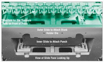
Double-action Slide. This press has two slides—one slide within the other (see Figure 6). Each slide has two connections to the eccentric shaft. The stroke of each is different and timed so the outer slide is the blank holder while the inner slide completes the drawing operation.
Figure 3. This drive is used when a continuous production speed of lower than 28 SPM is needed. It is good for heavy-duty applications, especially for stamping high-strength steels.
A double-action-slide press is used in deep-draw applications, such as beverage cans. In addition, it is the first press in an automotive press line for drawing the outer skin panels of cars.
Hydraulic Stamping Press
Hydraulic presses have advanced dramatically over the years with new technologies and improvements in electronics and valves. They are especially suitable for deep-draw applications, because they can apply full tonnage over the complete length of the stroke.
In addition, you can program the velocity that the slide travels as it closes the die.
You can program the return stroke for fast return, and you can adjust the stroke to any distance you need, thus achieving the maximum SPM available with the pump design.
A hydraulic press is powered by a hydraulic pump to a hydraulic cylinder or cylinders that drive the slide down. Pressure can be preset, and once achieved, a valve can activate pressure reversal so no overload can occur. With this press design and its applications, the die tends to guide the press, so the guiding systems do not have to be as accurate as with a progressive-die mechanical press. Hydraulic press production speeds normally are lower than those achieved with a mechanical press.
Common Stamping Press Terminology
- Blanking—The shearing or cutting of the complete parameter of any shape, called a blank, out of coil or strip material.
- Bottom dead center (BDC)—The lowest point of crankshaft (eccentric shaft) and press slide (ram) travel in a 360-degree press cycle.
- Die—An upper and lower tool set configured to cut, bend, form, draw, or coin metal that is placed between it. The press guides the tool set together under pressure.
- Drawing—A metal forming process in which a product is made by controlling sheet metal flow into a cavity with force from a punch. Forming of deep, recessed parts from sheet material by means of a plastic flow of the material worked in presses and dies.
- Piercing—The penetration of material that is placed between a punch and die and force is applied by a press. A precise hole is generated in the material to a required tolerance.
- Reverse load—The resultant force on the press when snap-through occurs.
- RPM—Revolutions per minute.
- Slide—Also called the ram, the slide is connected to the upper half of the tool set and moves up and down in the press frame. It is powered by the crankshaft. It also delivers the force (tonnage); hence the word ram in some countries.
- Snap-through—The point at which shear occurs when blanking or piercing metal.
- Stretching—Elongatation and reduction of metal thickness (not to be confused with drawing, in which the material thickness is maintained. Drawing requires metal flow, while stretching does not).
- SPM—Strokes per minute.
About the Author
About the Publication

subscribe now

The Fabricator is North America's leading magazine for the metal forming and fabricating industry. The magazine delivers the news, technical articles, and case histories that enable fabricators to do their jobs more efficiently. The Fabricator has served the industry since 1970.
start your free subscription- Stay connected from anywhere

Easily access valuable industry resources now with full access to the digital edition of The Fabricator.

Easily access valuable industry resources now with full access to the digital edition of The Welder.

Easily access valuable industry resources now with full access to the digital edition of The Tube and Pipe Journal.

Easily access valuable industry resources now with full access to the digital edition of The Fabricator en Español.
- Podcasting

In this episode of The Fabricator Podcast, Caleb Chamberlain, co-founder and CEO of OSH Cut, discusses his company’s...


