


Division Manager
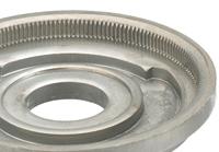
Figure 1: Incremental advancements in various areas, from tooling to press operation, have allowed engineers to fineblank complex parts, including those with 3-D features like bends and offsets.
For decades fineblanking has been known to produce parts with smooth, extremely precise edges. But the process’s current capabilities are quite different from when it was originally patented in 1923 and commercialized in the 1960s.
Cut edges can have as much as a 100 percent sheared surface, if required; while some taper remains, it is typically only half a degree. Its precision and repeatability make it perfect for manufacturing critical parts in moving mechanisms, producing near-net-shape, finished components right out of the press.
Fineblankng now can produce not only flat parts, but also those with 3-D features, often to size and position tolerances of less than ±0.025 mm. It also offers extremely high part-to-part repeatability; the first part and the millionth part are identical.
A confluence of technologies has made such parts a reality (see Figures 1 and 2). Without advances in presses, tooling, software, and lubrication, many of today’s advanced fineblanking applications simply wouldn’t be possible.
Fineblanking combines the concepts of metal stamping and cold-metal extrusion. It requires specialized presses, unique tooling, as well as workpiece materials that lend themselves to forming without inclusions and impurities.
To blank and pierce in conventional stamping, the punch contacting the workpiece induces highly compressive stresses and plastic deformation. The desired behavior of the material is to reach its rupture point abruptly, essentially breaking the material into the required shape.
While perfectly acceptable in conventional stamping, this isn’t accurate enough for precision parts. Many such components may require additional machining. Fineblanking can eliminate that requirement, and it also can produce parts that may have been made previously by costlier processes, like powder metallurgy or metal injection molding.
Unlike conventional blanking—which forces the metal to its ultimate tensile strength quickly—fineblanking does the opposite, promoting material flow like in an extrusion. A compound tool, with a blanking punch on one side and a counterpunch on the other, supports the workpiece throughout much of the stroke.
This tool allows the process to produce small holes and thin web sections relative to the material thickness. And with punches held in place by the counterpunch, they are always in the same position relative to other features blanked in the same station.
During the stroke an impingement ring, or V ring, presses into the material to prevent lateral material movement during piercing or blanking. The ring also ensures enough material is in the die cavity to create a fully sheared, straight edge.
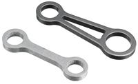
Figure 2: Cut edges can have as much as a 100 percent sheared surface, if required.
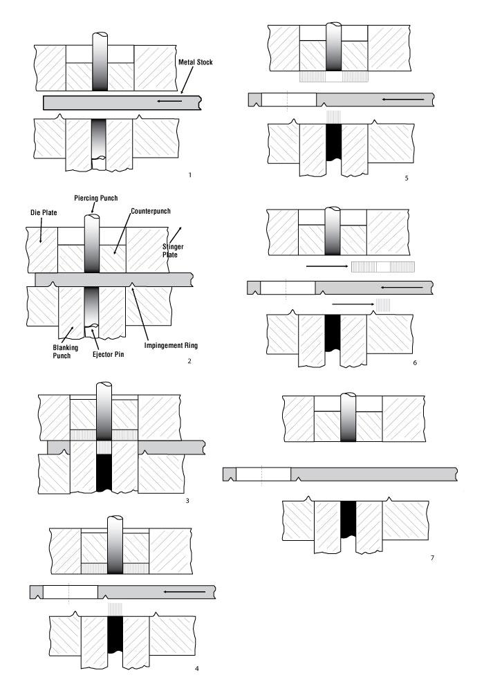
Figure 3 shows a simple sliding-punch fineblanking tool making a round washer with a hole at its center (1). In this setup, the tool closes and pressure embeds the impingement ring into the stock (2). The blanking punch advances until the part is fully sheared and resting in the upper die opening (3). In the same action, the pierce punch produces a hole in the workpiece. Simultaneously, the counterpunch pressure holds the part firmly against the face of the advancing blanking punch. This maintains flatness and produces a clean, precise edge. After this, the press relaxes all forces, the tool starts to open, and the ram descends by gravity.
Next, blanking pressure reverses, the punch pulls back, and an ejector pin pushes out the slug. At the same time, raw material advances to the next cycle (4). Finally, pressure from the counterpunch is reapplied, pushing the part out of the die opening (5), and air blasts or mechanical sweeps remove the part and slug from the die area (6). The system then is ready to start the next cycle (7).
The forming is a controlled extrusion of the workpiece material into the die cavity. The tooling clamps the workpiece in place to control its elastic flow. To that end, the die cavity has radiused “cutting edges” that allow the material to flow instead of being cut. In effect, the part is extruded out of the strip.
In fact, the material does not rupture until the punch moves all the way through the material thickness. Only in this controlled state, with the part edge pinched between punch and die components, does fineblanking allow the metal to rupture.
This fundamental difference makes the press itself quite different from conventional machines. Fineblanking presses must be especially rigid to minimize stretching and deflection during operation. This enables the use of tools with very tight fits and clearances, without concern for damage. Clearance between the punch and die is typically 0.5 percent of the material thickness.
Also known as triple-action presses, fineblanking presses perform three motions. First is the stinger pressure, which brings the two halves of the tool together and clamps the material with the stinger, or impingement ring. The second motion is the blanking pressure, which pushes the part into the die cavity. The third is the counterpressure, which applies the counterforce against the part throughout the blanking cycle.
Because the fineblanking press extrudes the metal, workpiece elongation characteristics are important. Many different carbon steels, alloy steels, stainless steels, and nonferrous metals can be fineblanked. Generally speaking, the lower the yield point of the material, the greater its elongation, which makes it more suitable for fineblanking.
The grain size and the level of spherical cementite structure also influence the process. The smaller the grain size and the higher percentage of spheroidization, the better the material will flow; this means the part will exhibit a better surface finish in the areas of the cut.
Fineblanking has evolved rapidly in recent years, mostly through various incremental improvements, and one of the most significant advances has been in the press itself. For many years fineblanking was labeled as a slow process requiring cumbersome hydraulic presses. Now new hydraulic presses can run at more than 50 strokes per minute (SPM), in many cases matching the speeds of conventional stamping of similar-thickness materials, all without jeopardizing the precision of the blanked part. Advances in tool steels and tool surface coatings, as well as extreme-temperature, oil-based lubrication and methods of application, have allowed the tools to keep up with the increased blanking speed.
Presses can be mechanical (for lower-tonnage applications), hydraulic, and, most recently, servo-driven machines. Modern hydraulic fineblanking presses can stroke much faster than their older cousins. For instance, the weight of the press bed, or table, traditionally has pushed the oil down on the return stroke. Now the return stroke may be driven by separate hydraulics.
Servo-driven fineblanking presses are just beginning to make an appearance in the field, and their fully programmable stroke is showing its advantages, especially when performing multiple forms. During the development process, a technician usually inches down the ram to determine the right shut height and other parameters for the application. With a servo-driven press, the technician can dial in the ram position, adjusting it in increments down to a fraction of a millimeter. The table remains at a constant pressure, and the technician can perform the operation in slow motion and in a controlled manner, to discover how the metal really is forming. This greatly reduces the time required for development work.
A fully controllable ram also allows technicians to vary the speed, moving slower during a portion of the form, then faster during the second portion of forming. Say an application calls for a 5-mm-thick workpiece material. The operation may require a 2-mm coin, then an extrusion to blank the part. The press ram can move slower for the coining operation, then speed up to perform the extrusion.
Many of today’s fineblanked components use progressive tooling, a departure from the single-station, compound-tooling concept the process is known for. Although many concepts of cold forging and progressive stamping have been converted for use in fineblanking tools, the process’s advantage remains the rigidity of the press-tooling combination. These rigidity requirements mean that the tooling and press can be only so large, which limits the die space and the number of stations.
vIn these situations, additional innovations have helped make fineblanking work. In many cases, several forming processes may need to take place in the same die station to keep relative feature positions intact. New concepts of punch holding as well as in-die fastening help overcome these challenges.
Additional hydraulic cylinders also may be integrated within the tooling. These can control the timing of certain operations, like the ejection of a part or slug or the application of an opposing pressure when forming a certain element, to maintain a controlled material flow.
When it comes to speed, the constraint quite often isn’t the press; it’s the tool—more specifically, the mechanisms used to eject a slug. So in many cases, slugs aren’t ejected but instead are dropped through the bottom of the die. A misplaced slug can cause a crash, so such setups often require sensors to ensure slugs evacuate at the right place and time.
Trends in machining also have pushed toolmaking forward. Modern wire electrical discharge machining (EDM) centers cut tooling components within a few microns. The components coming off the wire EDM require almost no secondary finishing; the traditional white layer on the tool component surface has been all but eliminated. High-speed machining operations can cut complex forms in tools, often in the hardened condition.
Adopting concepts from high-speed stamping and cold forging, fineblanking now makes extensive use of carbide tooling materials. These, along with the polishing of tool components and hard machining of die forms, have allowed fineblanking to create intricate 3-D forms.
To take advantage of new machine tool capabilities, 3-D modeling software and forming simulation have allowed tool designers to build and perform initial tool tryouts virtually. This has reduced optimization time and helped designers troubleshoot certain problems before any real tool is built, reducing tool-build costs substantially.
Although the basics remain the same, fineblanking advances in all aspects of the process—including tool machining, software, tool steels, tool surface coating, tooling design, press technology, and lubrication—have had a compounding effect.
Costs continue to go down due to better output; the complexity of fineblanked components continues to grow; and the process continues to help eliminate secondary operations and improve product reliability. All in all, that’s a good combination.


The Fabricator is North America's leading magazine for the metal forming and fabricating industry. The magazine delivers the news, technical articles, and case histories that enable fabricators to do their jobs more efficiently. The Fabricator has served the industry since 1970.
start your free subscription
Easily access valuable industry resources now with full access to the digital edition of The Fabricator.

Easily access valuable industry resources now with full access to the digital edition of The Welder.

Easily access valuable industry resources now with full access to the digital edition of The Tube and Pipe Journal.

Easily access valuable industry resources now with full access to the digital edition of The Fabricator en Español.
In this episode of The Fabricator Podcast, Caleb Chamberlain, co-founder and CEO of OSH Cut, discusses his company’s...


