


Contributing editor
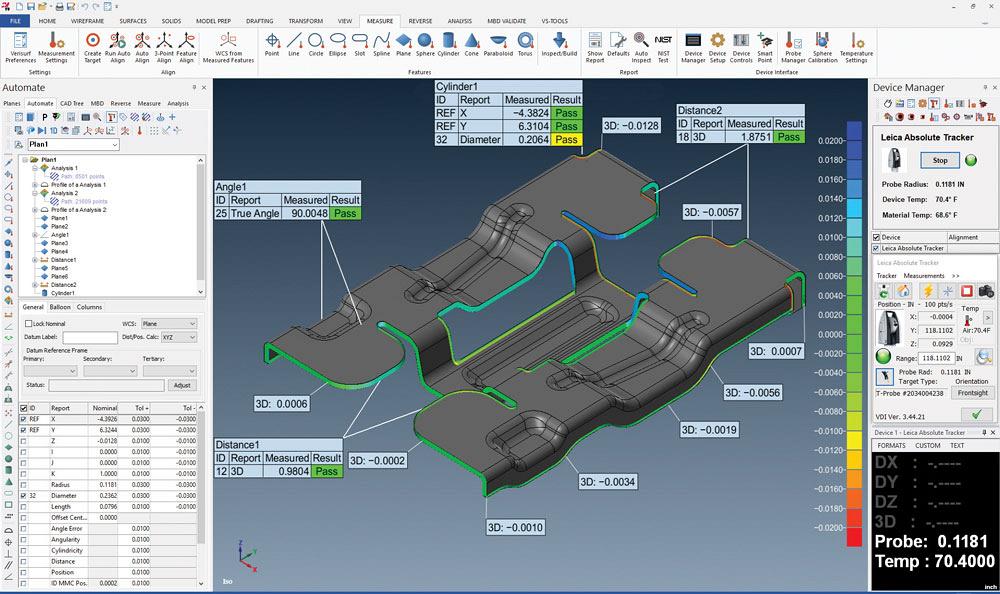
Model-based measurement and inspection software work with CMMs, enabling stampers to compare a first part to the nominal 3D CAD model quickly. Image courtesy of Verisurf Software, Anaheim, Calif.
In this era of recalls and defect-caused product lawsuits, automotive, aerospace, medical device, and appliance OEMs are increasingly demanding that their stamping suppliers provide defect-free parts—and sometimes levy penalties if the parts they receive are defective. Sometimes stampers are instructed to deliver their parts directly to their customer’s customers, making “100 percent defect-free” more critical than ever. They are expected to ensure accuracy, consistency, and repeatability.
After all, one bad part in a customer’s assembly process can create hundreds of hours of rechecks and additional production.
Many stampers contend that they cannot guarantee that defective parts won’t come off the press, but they can guarantee the bad parts won’t go out the door. They check, double-check, and triple-check the stamped parts to screen out the bad ones.
How? By running the parts through a series of quality verification devices. Stamping manufacturers may use a physical check fixture, vision system, coordinate measuring machine (CMM), or 3D laser scanner.
Or they may use several of them, as they are at Ultraform Industries (Read “Manufacturer uses servo press to hasten safety part production safely” in the May/June 2016 issue of STAMPING Journal). Every part and assembly undergoes at least three checks: First, the part or assembly is placed into a part check fixture to check that it fits within the part tolerance envelope. Then it is checked in a vision machine that looks for missing parts and properly located holes and features. Last, its dimensions are measured precisely in a CMM.
Many of the quality verification systems are integrated into the production processes, and checks are performed frequently throughout.
According to software manufacturer Verisurf, “Quality inspection and reporting used to be a disparate process isolated in a quality lab. Today it is much more integrated with the production floor through in-process inspection.”
What do each of these part quality systems check for? What are their functions and what are their limitations? What’s new in quality inspections?
Check fixtures are, well, a fixture in most stamping plants, and often are the first stage in quality checks (see Figure 1). Usually this is a manual, human visual inspection process, it is intended
to ensure that the part fits into the part envelope within a specified tolerance, that parts or features are not missing, and that it has all of its holes, in all the right places. Often check fixtures have a poka-yoke orientation, meaning that there is only one way to insert the part into the fixture.
According to Clark Fixture Technologies, these fixtures are ideal for verifying profiles and hole patterns and are an essential part of quality checks.
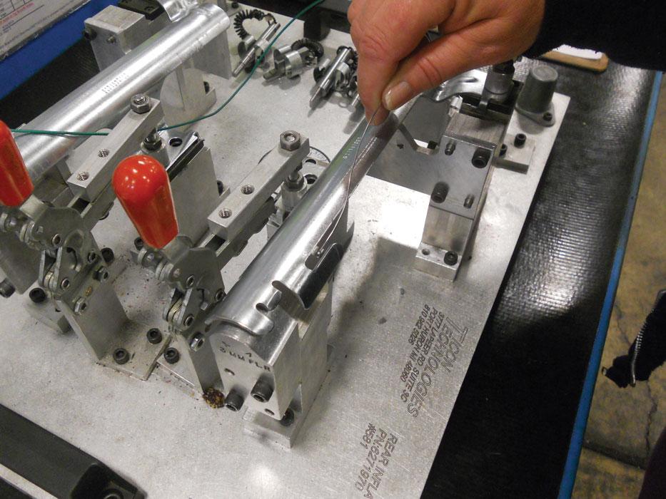
Figure 1
Physical check fixtures in full-contour or open pin style allow operators to quickly verify that a part or assembly fits within a part tolerance envelope. Photo courtesy of Ultraform Industries, Romeo, Mich.
“… we have found that, even with the advent of tube readers and similar devices, it is imperative to have poka-yoke fixturing on the shop floor. The envelope tolerance concept, whether in a full-contour or more open pin style, is the best means to verify quality.”
Clark also maintains that check fixtures allow entry-level participation. “It allows virtually any person with a minimum amount of training to know whether their work is acceptable. When applied at each stage of production, it also ensures the early elimination of defective parts.”
Mixed Materials. In terms of the materials used, Clark uses a combination of plastic and metal. Rather than manufacture the fixtures completely out of tool steel, the company makes them out of a durable composite material and positions hardened steel at the contact points, thereby saving on weight, manufacturing time, and cost, the company states on its website.
Many stamping manufacturers make some of their own check gauges in-house.
Vision inspection systems provide image-based inspection using a still or video camera, scanners, sensors, lighting, and software (see Figure 2). “Vision systems allow companies to conduct 100 percent inspection of parts for quality control purposes. Though not a new technology, 2D and 3D machine vision systems are now commonly used for quality control, automated inspection, robot guidance, and sorting,” stated the Global Association for Vision Information, AIA, on its website.
Vision systems can be used real-time in-process to provide a constant stream of information or they can be used postprocess. They perform any number of verifications, including measuring the part’s shape, identifying defects and unacceptable parts, and just confirming that all the pieces are present and are in the right position. Inline, they can also be used for ultrahigh-speed counting and real-time tracking.
Computer software processes images that capture data. The quality results can be displayed in a 3D computer model, using the measured dimensions of the actual part, and viewed from any angle.
Bio-inspired. At the Control 2018 expo in November 2018 at Messe Stuttgart, Prophesee, a French AI startup, introduced a neuromorphic vision system. The company’s patented technology introduces a new computer vision paradigm that mimics how the human eye and brain work, according to the company.
The bio-inspired, AI-based, event-based vision system is designed to dramatically improve the efficiency and intelligence of vision sensing and processing. The event-based method selects only the most useful and relevant elements of a scene, significantly reducing the power, latency, and data processing requirements imposed by traditional frame-based systems, according to the company.
The Onboard™ reference features the company’s video graphics array (VGA) camera and a standard Qualcomm® SnapdragonTM processor that can be quickly integrated into a production camera system design.
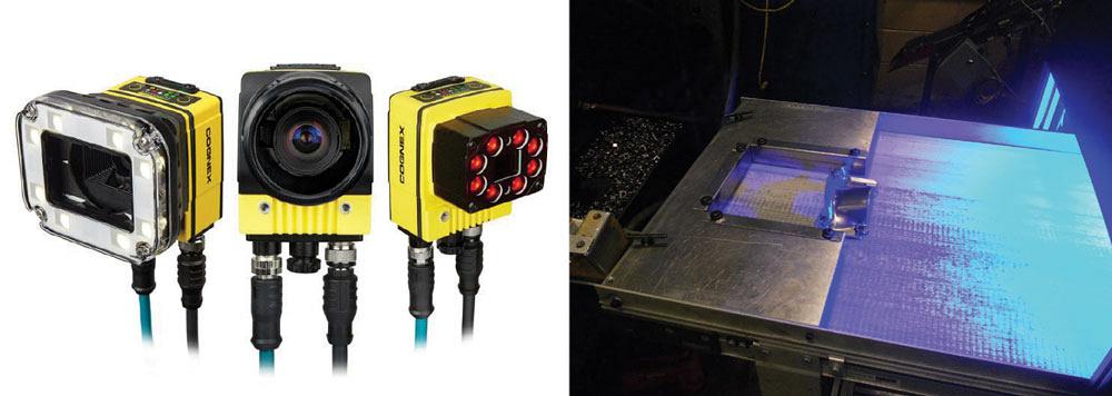
Figure 2
Vision systems can be used real-time in-process to measure the part’s shape, identify defects and unacceptable parts, confirm that all the pieces are present and are in the right position, count, sort, and track. Photos courtesy of Cognex, Natick, Mass., and Ultraform Industries.
Modular, Compact. Cognex Corp.’s In-Sight® laser profiler is a measurement system that verifies part dimensions (see Figure 3). The company’s vision tools, object detection, and the EasyBuilder® interface are intended to make the new profiler an intuitive and reliable option to obtain height, gap, position, and angle measurements intuitively and reliably. The profiler identifies even slight dimensional variations.
The laser profiler works by projecting a laser line onto the surface of an object, creating a cross-section profile of the object’s features. This profile can be viewed in the software interface. A CAD model of the part represents the critical dimensions that need to be measured. Using the extracted profile, the system analyzes the geometry to determine whether the object is dimensionally in tolerance and free of defects. Results can be monitored from any web-enabled laptop, table, or smartphone.
Cognex recently introduced its In-Sight 7000 series, a modular, stand-alone vision system. The second-generation system was designed to perform fast, precise inspections that keep pace with increasing line speeds, while its compact form fits into space-constrained production lines.
The unit’s modular design offers more than 400 different field configurations. The modular lighting and optics, including field-changeable autofocus, minimize the need for external lighting and allow users to configure the system to their requirements, according to the company.
Illumination. Smart Vision Lights, a designer and manufacturer of high-brightness LED lights for industrial applications, introduced a new cable that provides a directly wired connection between a light and Cognex’s second-generation In-Sight 7000 vision system.
Part of the company’s Camera to Light (CTL) series, the black cable works with the new pin layout of the IS7000 Gen2 camera series. SVL is developing a second version of the IS7000 Gen2 cable that will have a separate connector for power.
A CMM is considered to be a highly accurate way to measure dimensions.
The role of all CMMs, whether a laser scanner or contact probe, fixed or portable, is essentially the same: to measure dimensions accurately and provide data to the software for processing and reporting, according to Verisurf Software.
Verisurf introduced its new CMM MasterTM 500 at IMTS in Chicago. It is portable and programmable with model-based inspection capabilities that enable stampers to compare a first part to the nominal 3D CAD model quickly, the company says (see lead image).
The concept of model-based definition, which Verisurf Software developed for the PC platform more than 20 years ago, allows product development teams, manufacturing engineers, quality inspectors, and purchasing personnel to hold manufactured parts to a higher standard of quality and consistency, the company states. When stamping manufacturers use a model-based definition strategy, the CAD model becomes more than the nominal to which all parts are measured and inspected against. It keeps the all-important digital thread intact, from design to manufacturing to inspection and quality reporting. Everything that defines the part exists in a single digital archive, including how to manufacture and inspect the part.
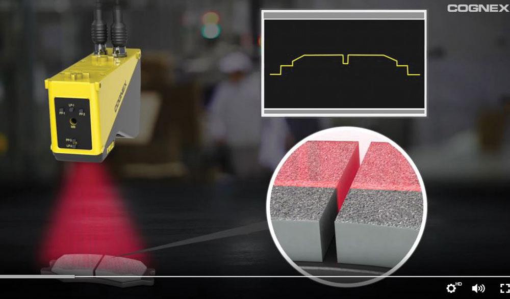
Figure 3
Cognex Corp.’s In-Sight laser profiler measures part dimensions, including height, gap, position, and angle. Image courtesy of Cognex Corp.
Verisurf President/ CEO Ernie Husted said that automated quality inspection and reporting are rapidly being adopted throughout all aspects of manufacturing. A key driver behind this is awareness of what stampers can now demand from quality metrics and reporting.
According to Husted, integrated quality inspection and reporting begins with inspection software and extends to CMMs and accessories. To maintain the digital thread, the software must be rooted in CAD and be able to open intelligent CAD files, annotate geometric dimensioning and tolerancing (GD&T) data, and inspect against the nominal datums. The inspection software should be open and offer the necessary level of interoperability to support current and future manufacturing inspection requirements, he said.
“At the end of the day, it is the job of inspection software to align and compare the nominal CAD model with measured points collected from the finished part, whether that includes a relatively small number of automatic or manually triggered contact points or noncontact scanned point cloud data containing millions of points,” Husted said.
3D scanners enable this direct comparison, according to Creaform (see Figure 4). “Using a portable 3D laser scanner will give any [quality control personnel] the capability to gather measurements of complex shapes to perform inspections by comparing scan data to the reference 3D model. Based on the accurate insights they get, they will be able to decide whether parts are accepted or rejected in no time.”
When defects are detected, stampers need to be able to go back to exactly where it went wrong to know if the problem comes from the design, the tooling, or the manufacturing process. 3D scanning lets them measure the tooling and part then inspect them to pinpoint defects rapidly and resolve them.
Hexagon Mfg. Intelligence has introduced the Optiv Performance 322 CMM, a customizable, upgradeable benchtop unit for the inspection of stampings and profiles.
Weighing less than 400 lbs., the fixed-bridge, moving-table machine is light enough to be placed directly on existing workbenches and relocated without calibration. Advanced temperature compensation technology calculates a correction value for measurement deviations to help ensure users get consistently stable results, says the company.
In addition, Hexagon has upgraded the ROMER Absolute Arm (see Figure 5). A key focus is on improved usability and versatility, said Product Manager Anthony Vianna.
A notable feature of the new Absolute Arm is its modular wrist design. It allows both the RS5 Laser Scanner and the pistol grip to be completely removed to allow probing in tight spaces, such as inside cavities. It can be reattached for laser scanning applications. The new wrist also now features a display screen that allows for measurement result oversight, profile switching, and calibration right at the point of measurement, reducing the time spent switching attention between the arm and its control computer.
3D scanners offer an additional utility beyond quality inspections, according to Hexagon and Verisurf.
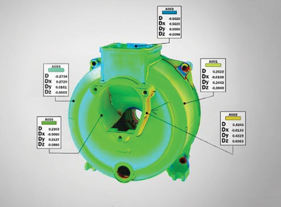
Figure 4
A 3D laser scanner gives quality control personnel the capability to scan measurements of complex shapes and compare them to the reference 3D model. Image courtesy of Creaform. Lévis, Quebec, Canada.
When only a legacy part or prototype is provided instead of a 3D CAD model, a 3D scanner and software can be used to reverse-engineer the part and convert it to a 3D CAD model. The model then can used as the virtual part for all tool and die design, inspection, and quality reporting throughout the entire manufacturing process.
Integrated, Continuous Inspections. Incodema employed available inspection technologies to implement GE quality programs in its operations, such as the operator-inspector program. This program requires each employee to deliver a product to the next process with zero defects. This approach has moved quality checks and responsibility from final inspection to each step of the process, including receiving, production, and shipping.
Gap and Flush. For today’s automobile manufacturers, aesthetics is a paramount concern. That was the motivation behind the installation of a new Cognex gap and flush inspection system at the FCA Brampton Assembly Plant in Ontario, Canada.
FCA used Cognex DS1300 laser profilers to verify that the gap between doors and panels was consistent and within 0.2 mm of the specification, and that the doors were flush or planar to neighboring panels within 0.3 mm on the Brampton-built Chrysler 300, Dodge Challenger, and Dodge Charger. An encoder connected to a Rockwell Automation PLC tracks each vehicle frame as it travels down the production line.
If only door “gap” measurements had been needed, the application could have been executed using In-Sight smart cameras. But the “flush” part of this system required that the doors and body panels be on the same plane. The profiler tool measures the Z-axis accurately to confirm that both body panels are on the same plane before the panels go to the painting station, according to a Cognex spokesperson.
AIA, www.visiononline.org
Clark Fixture Technologies, www.clarkfixtures.com
Cognex, www.cognex.com
Creaform, www.creaform3d.com
Hexagon, www.hexagonmi.com
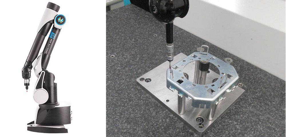
Figure 5
CMMs can be fixed or portable for improved usability and versatility. Photo courtesy of Hexagon Intelligence, Elgin, Ill., and Ultraform Industries.
Prophesee, www.prophesee.ai
Smart Vision Lights, www.smartvisionlights.com
Ultraform Industries, www.ultraformindustries.com
Verisurf Software, www.verisurf.com

The Fabricator is North America's leading magazine for the metal forming and fabricating industry. The magazine delivers the news, technical articles, and case histories that enable fabricators to do their jobs more efficiently. The Fabricator has served the industry since 1970.
start your free subscription
Easily access valuable industry resources now with full access to the digital edition of The Fabricator.

Easily access valuable industry resources now with full access to the digital edition of The Welder.

Easily access valuable industry resources now with full access to the digital edition of The Tube and Pipe Journal.

Easily access valuable industry resources now with full access to the digital edition of The Fabricator en Español.
In this episode of The Fabricator Podcast, Caleb Chamberlain, co-founder and CEO of OSH Cut, discusses his company’s...


