


Contributing Writer
 |
While designers took these limitations into account and designed the product to be forgiving at the ends of the channels, several factors over the past decade have caused the company to use roll forming less and less.
The first change to influence the feasibility of rolling these channels occurred 10 years ago, when automakers started asking for increased seat adjustment, as well as more foot room in the rear seat. This forced the designers to move the bearing stops closer to the channels ends, which are dimensionally unstable because of the stress induced by roll forming.
The second change occurred when the seat was required to carry the seat belt loads. Previously seat belts were fastened to the floor. This new requirement prompted the company to use high-strength, low-alloy materials and to add features to the shape, which resulted in increased stress in the channel when rolled.
 |
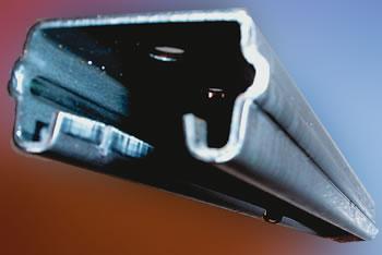
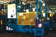
| Figure 1 The subsequent processes required pivot pins to be welded onto the side of the channel and the channel to be loaded on the paint line. |
The third change resulted from competition with European seat adjuster designers, who use stamped tracks. These stamped tracks have more flexibility in where openings can be located and how many features could be added to the channel. Roll formed tracks tend to distort when openings are located in the side wall of the channel, so components have to be added to the assembly when parts are rolled versus stamped.
Because of these product requirement changes, the company decided to re-evaluate its manufacturing methods. It determined that stamping a blank, forming it around a mandrel, and finishing with a roll mill to fine-tune the width dimensions would hold the critical channel characteristics-inside width, straightness, and flatness-and would allow the addition of features to the side walls.
The machine would comprise a blank feed mechanism, a four-slide hydraulic forming station, a hydraulic tabbing station, and a roll form station. The tooling in the forming station would be separate from the machine to simplify maintenance. Because internal channel dimensions were critical, designers decided to form the part around the mandrel, even though this would increase cycle time as the part was stripped off the mandrel.
 |
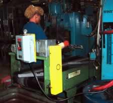
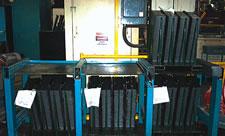
| Figure 2 Six different parts had to run on this new system, which required six different blanks and three different lengths. Each length had a left- and right-hand part, and the right-hand part carried a part number ID stamp and a part ID hole so that the forming machine could detect which blank was loaded. |
The subsequent processes required pivot pins to be welded onto the side of the channel and the channel to be loaded on the paint line (see Figure 1). The plan was to design a machine that would run at about half the cycle time of the pin weld station so it could feed the second pin welder with limited inventory in between.
The company found a supplier that could design, build, program, and wire the complete project. The supplier met twice with tooling engineers, product designers, and maintenance personnel to perform a failure mode and effects analysis (FMEA) on the process. After the supplier generated a basic design, it was reviewed in FMEA format to identify potential problems.
Quick changeovers were emphasized from the start of the process. Six different parts had to run on this new system, which required six different blanks and three different lengths. Each length had a left- and right-hand part, and the right-hand part carried a number ID stamp and a part ID hole so that the forming machine could detect which blank was loaded (see Figure 2).
 |
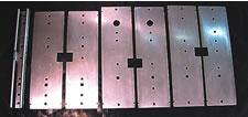
| Figure 3 This system allows the switch from right-hand to left-hand to take place in seconds. Changing from one length to another involves dialing in a new progression to the servo feed, pulling two location pins, loosening two C clamps in the subdie, indexing the subdie laterally in the master die set, reinserting the pins, and tightening the clamps -all of which happens without removing the coil stock. |
A master die set was built that contained a cutoff and incoming and outgoing stock guides. A sub-die set was installed that contained side-by-side tooling for the three different blank lengths. Three sets of gag punches were installed in the top shoe to switch the two punches and ID stamp for each right-hand part.
This system allows the switch from right-hand to left-hand to take place in seconds. Changing from one length to another involves dialing in a new progression to the servo feed, pulling two location pins, loosening two C clamps in the subdie, indexing the subdie laterally in the master die set, reinserting the pins, and tightening the clamps-all of which happens without removing the coil stock. This design has an average changeover time of 10 minutes versus the previous 45 minutes (see Figure 3).
Forming machine changeover involves transferring an errorproofing bar from one set of holes to another in the blank feeder stations, loading different blanks, and changing the form die when part length changes. The dies are held in with two pins and four bolts. Fold-out arms located on the side of the press aid pre- and poststaging of the die.
 |
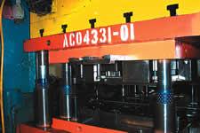
| Figure 4 The tab and the transfer stations are designed to change over automatically once the sensors read the first blank. The system works as long as a part is removed from the tab station before changeover starts. |
The tab and the transfer stations are designed to change over automatically once the sensors read the first blank. The system works as long as a part is removed from the tab station before changeover starts (see Figure 4).
The supplier built two machines that have run successfully for three years on a three-shift basis. However, after the start-up of the first machine, it became obvious that handling of blanks between the press and forming machine had to be improved.
Initially the operator manually placed the blanks in plastic totes, but this was labor-intensive and gave the operator no time to inspect the blanks. To resolve this issue, the supplier designed a special container to hold about 1,100 blanks in five stacks. A lead-in on each stack caused parts to stack automatically off the blank press, which helped to improve load time at the forming machine. Load times improved from 20 minutes per hour to 10 minutes per hour (see Figure 5).
The next step was to solve feeding problems that occurred when the blanks contained more than 0.020 inch of bow or twist. To resolve this issue, the supplier:
 |
| Figure 5 A lead-in on each stack caused parts to stack automatically off the blank press, which helped to improve load time at the forming machine. |
Another process problem occurred in the forming station when hydraulic hoses and valve bodies blew, and a filter broke out of the side of the tank when a weld fatigued, draining all the oil from the tank.
To solve the leakage problem, the supplier added a bracket to the filter to restrict vibration. As the aluminum valve bodies failed, they were replaced with steel valves.
In addition, the machine was reprogrammed to overlap the operations of the hydraulic system such that the valve for the next operation would open as the valve for the current operation was closing. An additional timer was programmed to stop the machine if the home switch on the current operation didn't indicate the stroke was complete within a certain time period.
Reprogramming forced energy from a destructive pressure spike-which occurs when a valve closes-into the next operation. The results were smoother, more consistent use of the hydraulic flow; reduced hose failure; and a three-second reduction in cycle time.
A third problem area was the servo linear actuator that transferred parts from the form operation to the tab station and the roll former. The servo actuator wore out, broke prematurely, and constantly faulted out. The supplier blamed the problems on vibration and too much magnetic field in the control cabinet. However, none of the corrective actions the supplier came up with resolved the situation.
The manufacturer then replaced the servo with a double-ended air cylinder and incorporated U-shaped, drop-in changeover blocks to set the travel distance for the various channel lengths. This increased the changeover time by five minutes but eliminated most of the machine downtime. The manufacturer also replaced the linear actuator, which failed every three months, with an air cylinder that has lasted more than a year.
By developing the process to best align with components requirements, the manufacturer now can produce a critical component of its product without an operator; the previous process required a skilled roll form technician.
Today the manufacturer has reduced inventory levels and changeover time and is producing a component in which some of the critical characteristics have achieved a fourfold improvement.
Tom Paisley is a toolroom manager with Dura Automotive Systems Inc., Stockton Seat Group, 301 S. Simmons St., Stockton, IL 61085, 815-947-3333, fax 815-947-3010, paisley.t@duraauto.com, www.duraauto.com. Dura Automotive Systems Inc. is a designer and manufacturer of cockpit subsystems and a supplier of door modules, glass systems, seat mechanisms and structures, and engineered assemblies.


The Fabricator is North America's leading magazine for the metal forming and fabricating industry. The magazine delivers the news, technical articles, and case histories that enable fabricators to do their jobs more efficiently. The Fabricator has served the industry since 1970.
start your free subscription
Easily access valuable industry resources now with full access to the digital edition of The Fabricator.

Easily access valuable industry resources now with full access to the digital edition of The Welder.

Easily access valuable industry resources now with full access to the digital edition of The Tube and Pipe Journal.

Easily access valuable industry resources now with full access to the digital edition of The Fabricator en Español.
In this episode of The Fabricator Podcast, Caleb Chamberlain, co-founder and CEO of OSH Cut, discusses his company’s...


