


Contributing Writer
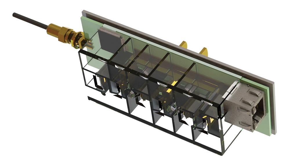
Figure 1a
The prototype has many exposed electronic components and is unsafe for operation.
Mind reading is not covered in the FAQs of your CAD owner’s manual, but it is a job requirement for the CAD jockey working in product development. It’s very similar to the way that my optometrist has to read my mind to determine what I see and like.
Through a better-or-worse process of elimination, he and I arrive at my improved vision. A similar process of elimination can be used to arrive at designs targeted for production.
When the CAD task requires delivering proposals as opposed to specifications, the modeling work is by nature temporary. A general guide for CAD work is don’t model detail unless it is critical to the decision-making process.
When a model is presented primarily as a proposal, the CAD jockey can postpone a great deal of detail. The assignment of part numbers, descriptions, revision control, file names—all of that can be preliminary in nature.
As a side note, a CAD model that is driving a 2-D production drawing needs to be tightly controlled when it comes to revision management and specification. Accidental edits that occur because of external relationships with other CAD models must be avoided. Speed in document control is not a necessity; the production environment is not the same as the product development environment.
With dozens of options relating to CAD techniques, any product designer must realize that some CAD tricks are slower to the finish line than others. Perhaps most important, some modeling techniques make it easy to explore “what if” scenarios with shape and materials.
Proponents of the model-it-for-production-at-all-times movement are
out there. To some extent that approach makes sense. The product development goal is exploration and iteration toward a better design. That does not preclude good CAD habits.
However, it would not be efficient to slow down the development process by mandating the creation of production-ready CAD models. If the work completed for a proposal does turn out to be production-ready, then that eliminates some delay in getting the product manufactured.
The phrase design for manufacturing implies that there is another way to develop products—design oblivious to manufacturing, perhaps. We could put primary emphasis on form and function and simply hope that materials and production processes can be developed to match. Hope is not a robust engineering principle.
At the other extreme, we could design with only fabrication of specific details in mind. That limits the product’s look and feel to whatever manufacturing process is at hand. We’re offering three examples of the consequences of that approach to design.
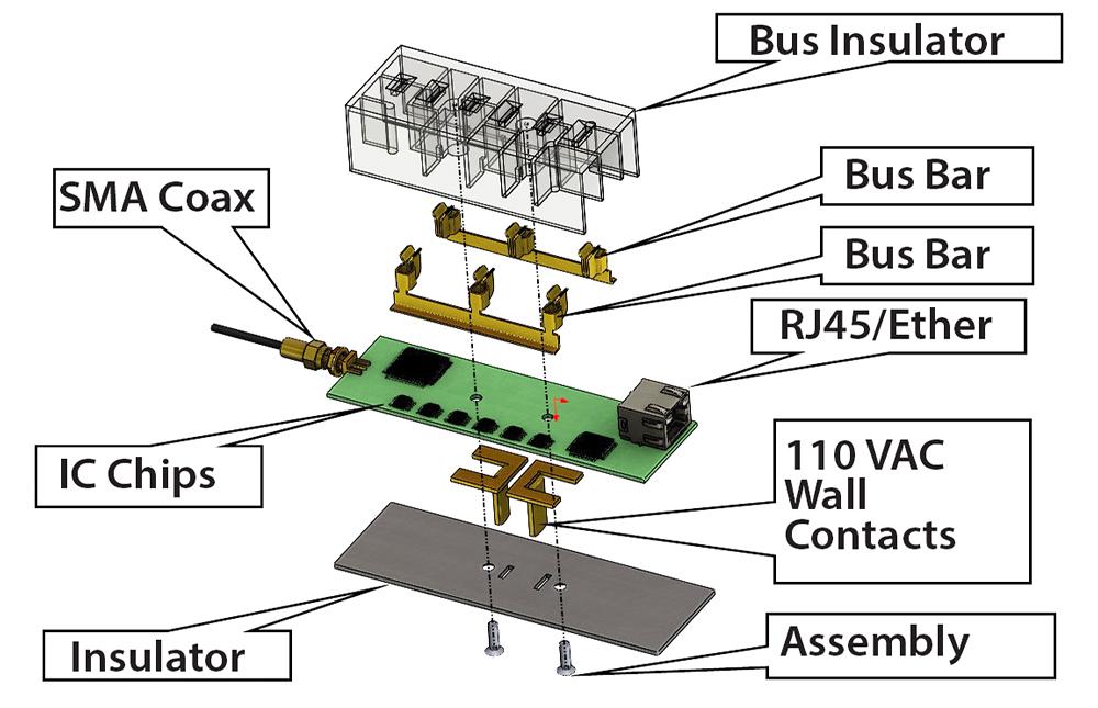
Figure 1b
The components in the prototype are shown. Our enclosure must wrap around these parts. Our goals are safety, reliable operation, and efficient production.
Modeling techniques that use complex webs of external relationships or even unconstrained sketches are acceptable for the sake of speed in arriving at the “look.” Parametric modeling speeds development when components that must be aligned remain so even when other parts of the assembly are moved or stretched.
As a phrase, design intent addresses what is to be delivered in terms of CAD. Specifically, it explains which parameters are likely to change in the CAD model to achieve a different shape, use a different material, or to switch from one manufacturing process to another.
Design intent is not static; it is a constantly moving target. In the early stages of product development, we want to quickly see what the product looks like. Just getting a blob up on the screen for conversation is the goal; the modeling techniques used might be of marginal value when it comes to future editing or documentation.
As the design matures, the models that were quickly thrown together receive more thoughtful treatment. Some models might even be thrown away and remodeled from scratch under the prevailing design intent.
There is no separation between design intent and design for manufacturing other than opportunity. Design for manufacturing should emerge in mature designs. To put this development intent wisdom into context, we are going to have a customer arrive with the prototype shown in Figure 1a. Our task is to design an enclosure for the product. Someone else will write software and create a market for it. Figure 1b is an exploded view of the customer’s prototype.
We don’t know everything about this product, but we do get to know some general details. This product plugs into a standard U.S. wall outlet. It provides a place to plug in as many as three two-prong lamp cords. The product can be connected to a computer network via CAT-5 cable. It also features a coaxial cable connection. A circuit board with some integrated circuit (IC) chips on it is part of the design. We can only suppose that this thing monitors and switches its three outlets on and off with remotely controlled software.
Our imagined customer is clear on what needs to be inside the enclosure. However, the outside is a great mystery. We are tasked with offering the customer three options. After the customer decides on a direction, we may be tasked with refining the design for production.
Unlike real life, we have the advantage of seeing the finished proposals before we begin. Also unreal is the idea that we’d start without a clue about target production quantities or mechanical goals.
Figure 2a shows a version of an enclosure that is primarily molded plastic, front and rear. Figure 3a shows an extruded aluminum frame with plastic front and back plates.
Figure 4a shows a sheet metal enclosure with insulating plastic front and rear panels. From the get-go we know that at least two of our design proposals will be rejected. We must not waste time on irrelevant detail in any of our proposals.
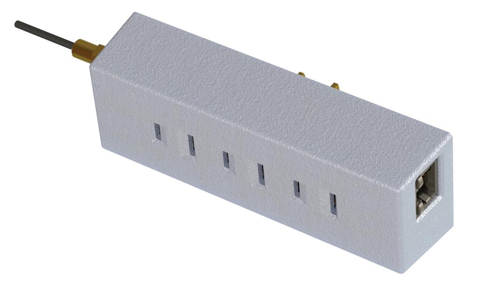
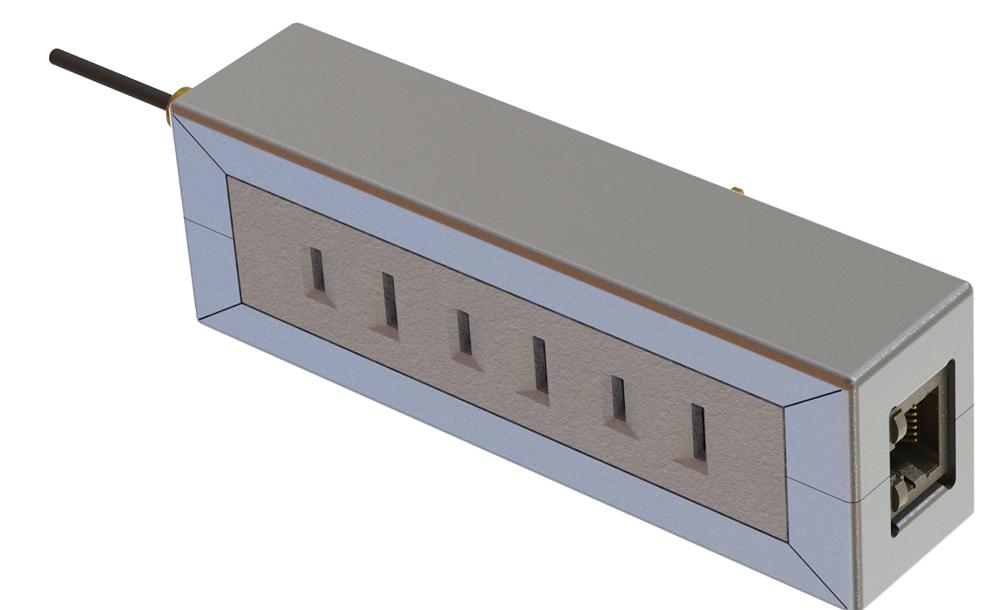
Figure 2a
This proposed design wraps the front with a plastic insulator and covers the back with a plastic insulating plate.
An early step in the design process is to sort out what we can and cannot change. As specific examples of what we cannot change, consider industry- standard wall outlets, electrical insulation requirements, safety regulations concerning consumer electronics, the number and size of the integrated circuits, and the kinds of connectors that the customer wants to use.
We are given some latitude with the shape of the enclosure; we can move the IC chips around a little bit to clear mounting screws and so forth. The customer has given us a target circuit board size range. We also can select materials. Electrical safety is an overriding consideration so we’ll use plastic where needed.
As we start the CAD work, our goal is to use existing models as much as possible. We can download models for the RJ45 connector as well as for the SubMiniature version A jack. A CAD library will provide the hardware models for things such as nuts, screws, and washers.
As we collect the existing models for the items that we know we must have, we will start assembling them to model the circuit board. After the circuit board is put together, we’ll start wrapping it with an enclosure.
Even though our circuit board assembly is essentially common to all three of our planned enclosure designs, we want to reserve the ability to have a unique board/IC chip arrangement for each design. We are going to eschew the CAD technique of using subassemblies in this proposal model. That allows each version of the proposal to be completely independent of the others. When the model goes to production, it is likely that it will be reorganized with subassemblies to better document and more realistically represent the product.
The general plan is to model a design and then use that as a starting point for the next design. We’ll save and rename files as needed to maintain three distinct projects. For this exercise, I’m putting all of the CAD files for these three designs into a single folder. I could have created separate folders so that file naming isn’t so fussy. However, speed is a primary consideration. The plan is to use the same component model in all three assemblies unless it must be unique.
The customer may not be attuned to all of the information that contributes to a good design process. Important information includes goals for production quantities, targets for price, methods of distribution and installation, maintenance and repair, and the anticipated assembly resources. If the overall strategy for the product is low volume with a high price tag, then the design may sacrifice some efficiency in material and assembly for the benefit of low tooling cost or shorter lead-time.
At another product strategy extreme, high volume with a low price tag likely will benefit from dedicated tooling and automation in the fabrication process. In this case, efficient use of material and production labor is a separate consideration from one-time tooling costs.
This project has some custom parts that will be identical in all three proposed designs. In Figure 2b we see two prongs that plug into the wall outlet. They are similar, but are different sizes. Additionally, the two bus bars each have three blade contacts.
The copper parts will be soldered to the circuit board. The two bus bars mount on one side, while the two wall plug blades solder to the other side of the board.
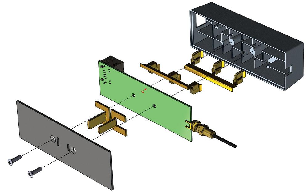
Figure 2b
The front plastic body has pockets that hold the copper contacts in place. Copper parts are soldered to the circuit board. A pair of screws clamp the assembly together.
It may be difficult to discern that the copper parts are modeled accurately as sheet metal, and they will unfold for manufacturing. The goal was speed, and doing it “right” from the get-go was indeed speedy.
Plastic Theme. The need for electrical insulation around the copper parts is a major design goal in this product. Making the entire enclosure out of insulating plastic seems like a good starting point, as shown in Figure 2a.
For the all-plastic version of this enclosure, the front section serves two primary functions: insulation and stabilization of the copper parts and protection of the circuit board and jacks from damage.
The cutout for the RJ45 connector is shown in Figure 2b. This side-wall hole feature will require a slide in the tooling and is expensive. The mouse-hole notch for the SMA connector is less expensive. The customer will have to verify that the tooling and exotic slide expense are justified.
Potentially, this all-plastic enclosure design has a safety and weight advantage. It might be the quickest to assemble. On the downside, it represents a significant investment in injection molding tooling. As a blessing, it may have the lowest unit production cost of the three designs if tooling is not a consideration.
The CAD model for the front plastic insulator shown in Figure 2b is fairly detailed. All draft angles for extraction from the injection tooling are modeled. Surface texture was added for realism. Somehow the tapped holes for the mounting screws were omitted.
In this example, the labor of detail was beneficial for verifying clearance/contact with IC chips and the board, as well as for visualizing the finished product. These observations are offered as confirmation that no clear lines of demarcation are present when it comes to design intent or CAD jockey discipline.
Extrusion Theme. The exploded view in Figure 3b shows the extrusion frame along with the common parts: circuit board, copper contacts, and cable jacks. The designs for the front and rear plastic insulating parts have been updated to match the extrusion.
In evaluating this extruded frame design, we see that the front insulator represents a significant investment in tooling. However, it has less surface area than the all-plastic proposal, which probably translates into lower tooling cost. As with the alternate insulator shown in Figure 2b, it could be prototyped with a 3-D printer.
The extrusion will have an initial tooling cost, and it also requires some significant secondary machining operations. The extrusion concept makes it practical to add heat sink fins to the design. The customer might be delighted with that idea.
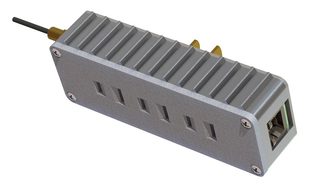
Figure 3a
The heat sink fins on this proposed design are molded into the aluminum extrusion. Secondary machining operations cut the mouse holes for the RJ45 and SMA connectors. The design is easy to upgrade—just swap out the front plate.
This design also has better electrical shielding than the all-plastic version. The look, heft, and structure of this extrusion-based design are substantial. If the military needs one of these things, this is it!
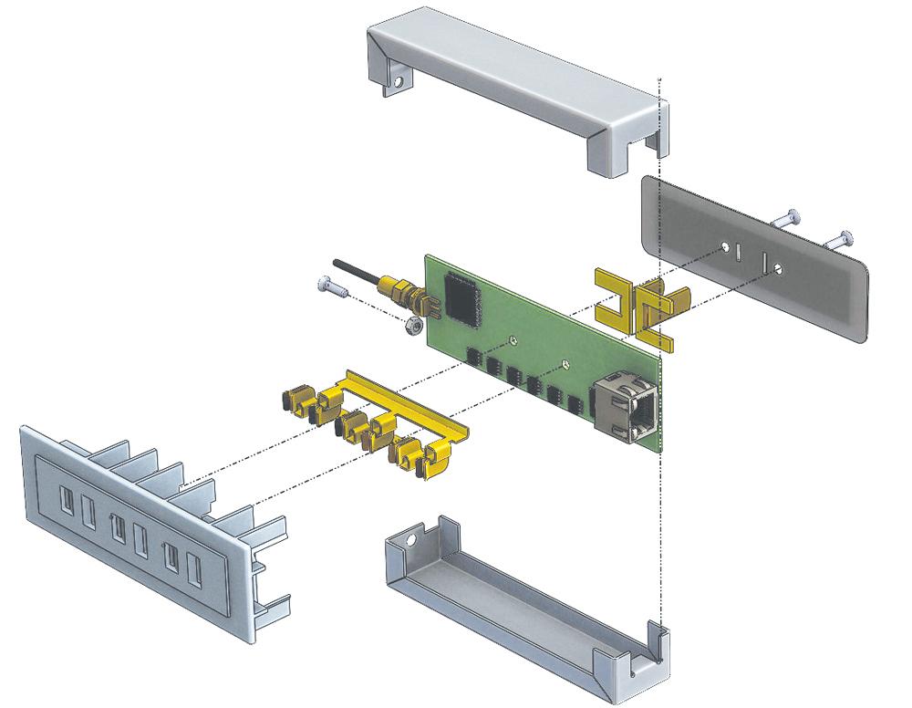
Sheet Metal Theme. The sheet metal enclosure shown in Figure 4a has a two-piece frame. The corners have a visible split seam, but are coined slightly to give a burr-free roundness. The actual forming technology is the result of a press brake accident I had many years ago. As a designer, I’m pretty sure it can be re-created with a little bit of dedicated tooling and some urethane block.
Even though this model looks like a sheet metal frame, it is not production-ready. The model will not unfold. It is a multibody part modeled with a wandering mess of CAD features. The jogged tab alone required almost a dozen modeling steps. This observation is offered as confirmation that not all “quick” models are completed quickly—if at all.
In this design, the proposed sheet metal comes in contact with the body of the RJ45 connector for shielding. Those same contact tabs act as hooks to lock the sheet metal in place. The exploded view in Figure 4b reveals more internal details.
The sheet metal “hooks” into the front plastic insulator near the RJ45 connector. As the sheet metal is pressed into place, a snap hook in the plastic deflects and then latches onto the sheet metal tab. At the opposite side, a screw and nut clamp the sheet metal together against the front insulator. The nut drops into and is trapped in a channel molded into the front insulator.
With just a single screw for assembly, this design goes together more quickly than the extrusion version does. The tooling and setup for the sheet metal parts are an improvement over those for the extrusion, but this version is not quite as strong as the extrusion.
Of the three designs, this sheet metal theme has the best potential for low tooling expense and shortest lead-time.
When I say “worse” to my optometrist when he asks how my vision is when I look at the faraway chart, we shed no tears nor do we experience angst. When I say “better,” we celebrate in the briefest sense. When the customer announces that a proposed design has been rejected, the CAD jockey is merely grateful for the decision and does not throw furniture around the room.
In presenting these three design ideas for review, I cannot help but be fond of certain ones. Some of them are buried in the CAD, such as the idea for the heat sink, where I created a path and equally spaced a body along it. On the aesthetic side, I simply prefer the sleek look of the sheet metal over the other design proposals.
While my opinions and insights might contribute to the selection process, the presentation is not about selling an idea, but rather selecting a preference. As the customer evaluates the proposal, a consensus will emerge. In the speediest case, one or more of the proposals will be a hit. A slower outcome involves creating a new set of proposal models with different characteristics. Even if no targets were hit, at least some bad ideas were eliminated.
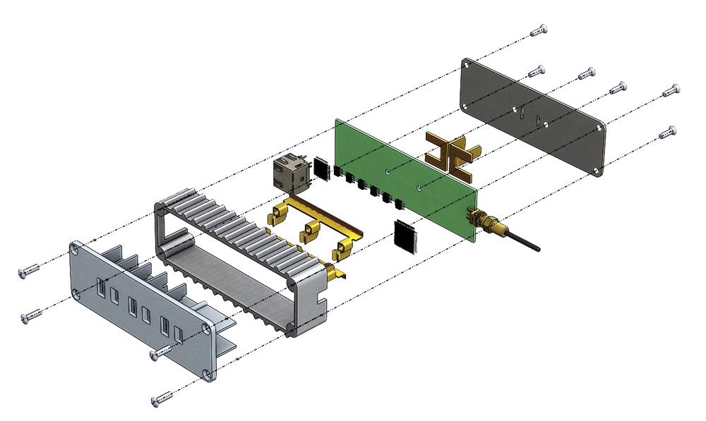
Figure 3b
The front insulator is easier to mold than the one shown in Figure 2b. The extruded frame is sturdy. On the downside, a lot of screws are needed in this assembly.
Static images are important, but 3-D is more revealing. The use of software to view 3-D models can expedite design review and selection. Those involved in the review could examine the 3-D model on their own and at their own pace in preparation for a collective review meeting.
Gerald would love to have you send him your comments and questions. You are not alone, and the problems you face often are shared by others. Share the grief, and perhaps we will all share in the joy of finding answers. Please send your questions and comments to dand@thefabricator.com.


The Fabricator is North America's leading magazine for the metal forming and fabricating industry. The magazine delivers the news, technical articles, and case histories that enable fabricators to do their jobs more efficiently. The Fabricator has served the industry since 1970.
start your free subscription
Easily access valuable industry resources now with full access to the digital edition of The Fabricator.

Easily access valuable industry resources now with full access to the digital edition of The Welder.

Easily access valuable industry resources now with full access to the digital edition of The Tube and Pipe Journal.

Easily access valuable industry resources now with full access to the digital edition of The Fabricator en Español.
In this episode of The Fabricator Podcast, Caleb Chamberlain, co-founder and CEO of OSH Cut, discusses his company’s...


