


Contributing Writer
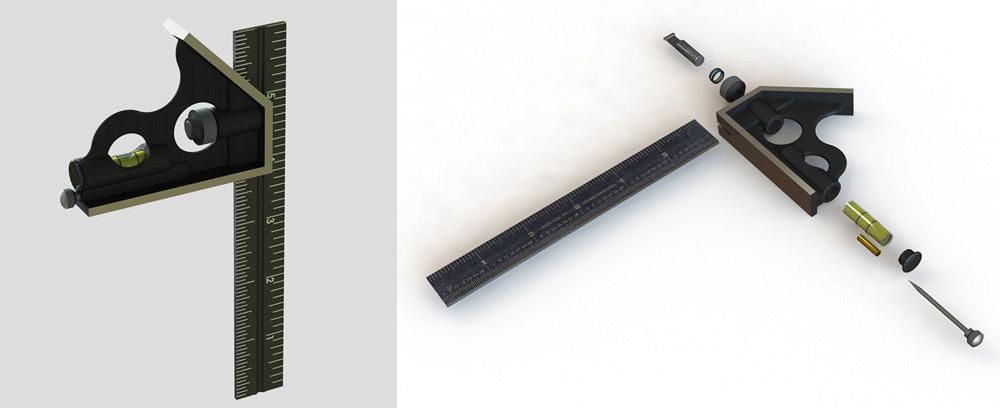
Figure 1
This 3-D model works well for visualization. It does not work as well for specifying where the parts come from, how big they are, or how to assemble them (left).
This square is modeled as an assembly of parts. Each component requires adequate documentation (right).
A 3-D CAD model can be great for the purposes of visualization. However, its shape alone does not provide sufficient documentation for fabrication.
Consider the combination square shown in Figure 1a. This 3-D model is detailed sufficiently to represent a physical object. This 3-D CAD can be used to generate a variety of images for illustrating assembly steps or promoting the product in other ways.
The 3-D CAD software used in support of this article creates digital files for several different functions, some of which represent parts, assemblies, or 2-D drawings. Because of the dependent relationship between these files, the software dictates elements of the workflow. An aficionado who favors multibody modeling would follow a slightly different workflow from that described here and, therefore, would skip some assembly modeling. We’re focusing on producing a bill of material (BOM). Furthermore, the following outline for CAD work covers a wide variety of projects using fairly basic modeling techniques:
The combination square in Figure 1a is shown in an exploded state in Figure 1b. These components could be assembled on a production line. The BOM would include a ruler, a head kit, and a scribe. The head kit includes a spring, knurled nut, clamping stud, level vial, snap cap, and head casting. Each of these components must be obtained in some manner—purchased off-the-shelf, produced in-house, or subcontracted per proprietary specification. Our job is to make the purchaser’s job easier.
The suppliers feeding an assembly line for this hand tool would include a foundry, machine shop, spring winder, metal stamper, plastic extruder, metal plater, and a paint shop.
In our scenario, each component will need to be documented completely for procurement, fabrication, and assembly. We won’t be directly involved in designing the tooling or fixtures. However, the 3-D model will be provided to the suppliers as part of the product’s manufacturing specification.
Avoid waste. Waste includes excessive levels of detail in the virtual prototype. Don’t model it unless it is necessary to do so. To illustrate some of the considerations in deciding how much detail to put into a CAD model, off-the-shelf components are good candidates for quick work with scant detail.
The head assembly shown in Figure 2 includes some items that must be custom-fabricated as well as a few that might be available off-the-shelf somewhere. By the way, we assign our own part number to everything, even though the supplier might have a different part number for the same item.
As an example of an off-the-shelf item, consider the level vial. It is identified as Item 3 in the BOM shown in Figure 2. Manufacturers of such level indicators can be found on the Internet. It would be ideal to use their ready-for-download CAD model for our visualization and delegate all of the fabrication and drawings to them. Figure 3 is a screen shot of some simple data entry within the model of the vial. That’s all that is needed to inform purchasing and complete the documentation effort for this item.
For a time budget, 20 minutes is needed for the essential modeling for visualization and another 30 minutes to add cute detail like bubbles and transparent surfaces. Finding an online source and filling in the custom properties form might take another 30 minutes.
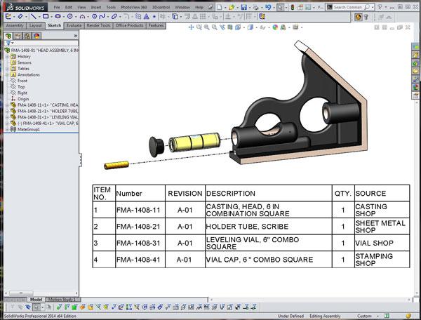
Figure 2
The head assembly has several parts that are permanently attached. Some items require full modeling detail, while others can just be placeholders for bill-of-material entries.
However, if the product absolutely requires a custom vial, then the 3-D model must be completely detailed for fabrication of the vial body, adding the marker lines, filling with an oil-like substance, capping, and sealing. We should probably specify leak check and verification of bubble calibration, fluid purity, and surface condition. Of course, the legal team will verify that no patents are infringed by this design.
Fortunately, we’re using common off-the-shelf vials in this scenario. For the purposes of visualization, a quick model of the vial included a stationary bubble. As a side note, the CAD effort to model a bubble that moves realistically is significant and is cited here as an example of excessive detail.
The BOM table in Figure 2 does not show any glue to hold the leveling vial in place. This is an oversight, and we’re glad you caught that error. The BOM does show a press-in cap—Item 4—which hides the glob of glue that is retaining the vial. Such caps are made from thin sheet stock and are produced on progressive-die stamping machines. In this scenario, we’re purchasing off-the-shelf caps and pretending that they are painted the correct color. Figure 4 shows the 3-D CAD model for the cap in progress.
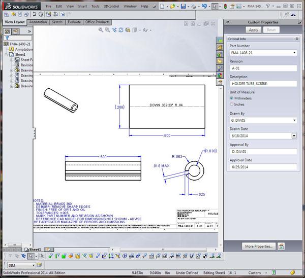
The scribe holder—Item 2 in the head assembly shown in Figure 2—is just a little brass roll pin. We’ll treat it as a custom part. A fabrication drawing, complete with flat layout, is shown in Figure 5.
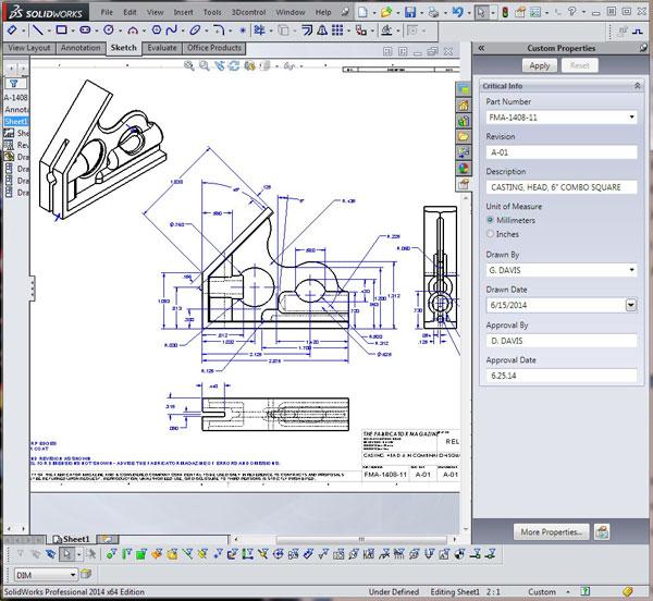
The final quality assurance drawing for the casting is shown in Figure 6. Additional drawings showing the painting, removal of sprue trees, and final machining are not included with this article but would be needed for the time estimate. The 3-D modeling for this casting will include draft angles and parting lines.
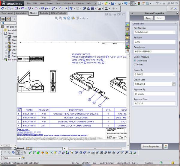
The fabrication drawing for the head assembly is shown in Figure 7. This drawing shows how to press in and glue the parts that are permanently connected to the casting. All of the modeling work has been considered in previous estimates, so the time budget for this drawing covers exploded views, animations, and step-by-step narrative instructions.
The BOM table on the drawing in Figure 7 is generated from the information stored in the models for each component. The work at this stage is just to verify that the data is complete and accurate.
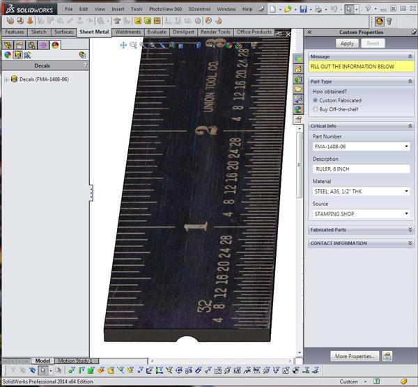
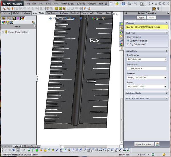
The 6-inch ruler required for this product will be a custom part. It could be machined sheet metal. However, the clamping groove and embossed tick marks are candidates for a progressive die in a stamping press. When considering how much effort to put into the CAD model for the ruler, a CAD jockey cannot always know how the part will be fabricated. In that scenario, more detail in the model is probably better than less.
As a demonstration of maximum and minimum modeling detail, one side of the ruler model has no detail except for a decal that makes it look finished with tick markings (see Figure 8a). The opposite side of the ruler is accurately modeled with extruded cuts for all of the lettering and tick marks (see Figure 8b).
The “decal” in Figure 8a took 10 minutes to complete. It involved scanning an existing ruler and pasting that image onto the surface of the model as a decal.
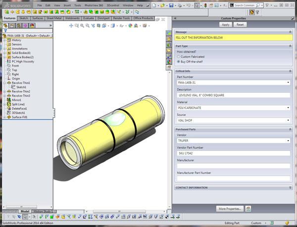
Figure 3
The leveling vial is purchased off-the-shelf and only needs to look pretty. No vials will be made based upon the 3-D details in this model. All that matters is the data entry regarding
where to buy it.
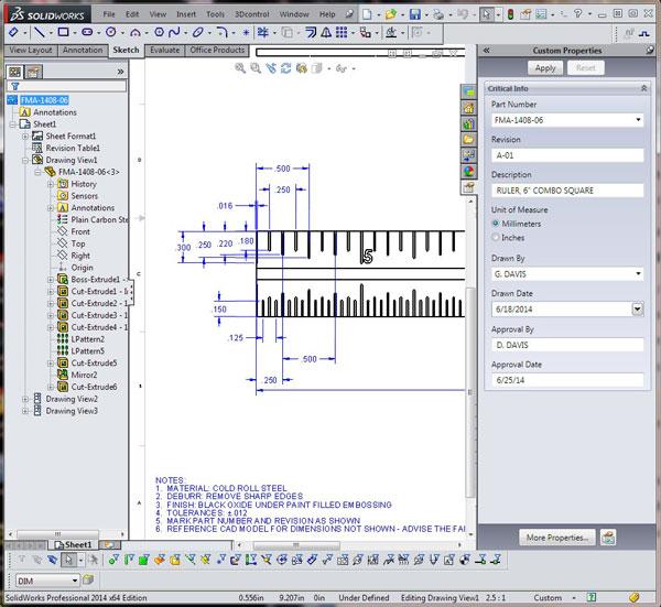
The “accurate” side in Figure 8b took much longer to complete and is made up of cut extrudes, patterns of cut extrudes, and patterns of patterns. We were pleased to stop at 1⁄16-in. intervals and not to model 1⁄32-in. intervals. At a casual pace, it took 45 minutes to plan and model the tick marks for one side of the ruler.
Even though the decal modeling technique was quick, it is not helpful for manufacturing. That’s where the detailed modeling pays off. The drawing in Figure 8c uses dimensions imported from the ruler’s model. That trick reduces the labor of making these tedious drawings. Even so, the 2-D drawing for just one side of the ruler could take 30 minutes.
The five machined parts—head casting, scribe, scribe holder, nut, and stud—are modeled with full detail for fabrication. The scribe is modeled as a shaft with a swaged-on head, but the knurling on the head is just a texture, not an accurately modeled feature. This saves some time in modeling and having to refresh the CPU. Also, it does not make the 2-D drawing annotations that much more difficult.
Similarly, the knurled locking nut is physically the correct shape and size with representative knurling and threading. It is good for the modeling effort and only a slight compromise in fidelity on paper.
The locking stud is modeled with full detail. This item could be forged or carved from a billet. Either way, it has embossed tabs to help with the ruler engagement, and one end is threaded. It has an embellishment to add the lead-out on the threading with a tapered helix. When you open a CAD model like this, we hope you appreciate this type of CAD trick.
Lastly, the 3-D model for the spring is a bit of a compromise between modeling effort and need. The starting and ending coils on the spring are flat and tight in a visually appealing way. However, the overall length of the spring is modeled only in the compressed state. For the purposes of this scenario, the spring will be treated as a commercial off-the-shelf item. With that in mind, a much simpler model for the spring could serve as a placeholder. (In retrospect, a considerable amount of time was wasted on modeling this spring. Even more time could have been wasted creating the uncompressed version of this spring model.)
In addition to the effort going into modeling the parts, effort must go into administrative chores such as creating folders, naming files, assigning part numbers, descriptions, and so forth.
For this scenario, we developed the shape and function of the combination square using an assembly of virtual parts. Such models are easy to rename and otherwise manipulate from a CAD administrative perspective. After the developmental modeling is completed, the virtual parts are given useful names and then saved as normal—that is to say, external—components in anticipation of distribution to third parties.
To verify that the data entry is complete, it can be helpful to insert a BOM table into the 3-D assembly as a preview and data entry point.
With the modeling, file naming, and data entry completed, the next stage in the workflow is the drafting of the 2-D drawings for fabrication. For off-the-shelf items, such as the vial and the spring, no drawings will be needed other than to mention them in a BOM or in step-by-step assembly instructions.
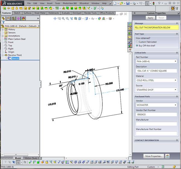
Figure 4
The press-in cap is also a purchased off-the-shelf item. Again, data entry is an important detail.
Using the Design Checker to verify the correct formats of notes and proper spellings is a recommended practice. Having another human review the work prior to committing to raw materials is generally a good idea. Errors and omissions on drawings are challenging to eliminate.
Gerald would love to have you send him your comments and questions. You are not alone, and the problems you face often are shared by others. Share the grief, and perhaps we will all share in the joy of finding answers. Please send your questions and comments to dand@thefabricator.com.


The Fabricator is North America's leading magazine for the metal forming and fabricating industry. The magazine delivers the news, technical articles, and case histories that enable fabricators to do their jobs more efficiently. The Fabricator has served the industry since 1970.
start your free subscription
Easily access valuable industry resources now with full access to the digital edition of The Fabricator.

Easily access valuable industry resources now with full access to the digital edition of The Welder.

Easily access valuable industry resources now with full access to the digital edition of The Tube and Pipe Journal.

Easily access valuable industry resources now with full access to the digital edition of The Fabricator en Español.
In this episode of The Fabricator Podcast, Caleb Chamberlain, co-founder and CEO of OSH Cut, discusses his company’s...


