


Contributing Writer
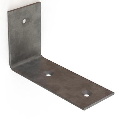
Figure 1a: This L-shaped bracket is something any shop can make with basic metal fabricating skills and tools.
This edition of Precision Matters continues our detailed examination of estimating as a business process. The previous edition discussed the estimator’s role in translating costs into prices: Cost is what you pay, price is what you charge.
At this point the estimator has a documented commitment to schedule and price, and the estimate is ready to be delivered to the customer. We now turn our attention to the presentation of price quotations. That is to say, how should the data be formatted for delivery to the customer?
For the sake of discussion, we’ve dissected the estimator’s job into a dozen tasks. In reality, these tasks may overlap or evolve in different sequences. As a review, here is a brief outline of how we’ve dissected an estimator’s job:
If we were to compare job descriptions for an estimator and a salesperson I would point out that estimators are pretty much focused on internal affairs whereas salespeople are building external networks of demand for the job shop’s time.
Not all job shops have the luxury of job descriptions or dust collectors like organizational charts. Extremely lean organizations might be compelled to have one soul handle many overlapping areas of responsibility. Our goal is to isolate the salesperson from the estimator, even if “they” coexist in the same skull. We do this because the salesperson wants to make the customer happy. We remove the temptation to negotiate the price for the sake of the relationship. The salesperson—allow me to use the title “customer service agent”—must keep the customer happy by doing things that support the efficiency of the transaction. The estimator’s cost estimate and the company’s policy for profits set the price and schedule; these are not negotiable as far as customer service is concerned.
The customer service staff wants to help both the job shop and the customer’s buyer succeed. Efficiency matters. Buyers appreciate clear communication as well as attention to detail.
Let’s review an ideal flow of information between our job shop and a customer. The customer’s buyer initiates the transaction by sending a request for quote (RFQ) to the job shop. Customer service conveys that RFQ to the estimator. The estimator performs the math and presents the data to customer service. Customer service delivers the price quote, also known as a bid, to the customer. The hope is the customer responds with a purchase order (PO). If we do get a PO, we’ll build the parts and send an invoice to the customer. The customer responds to the invoice with payment to us.
With that general information flow in mind, it seems that each buyer has a preference for how they would like to receive responses to their RFQ. The price quote can be delivered in several formats: paper, fax, e-mailed PDF, web page, text message, tweet, phone call, or face-to-face meeting.
We task our customer service with ascertaining exactly what information the customer wants us to include in the bid, as well as how to deliver the price quote.
When it comes to performing the math, the estimator will need to know how the buyer wants to deal with one-time expenses. The buyer might want to have nonrecurring charges shown as separate line items. That same information could instead be included in the piece-part price. The estimator needs to know this fact.
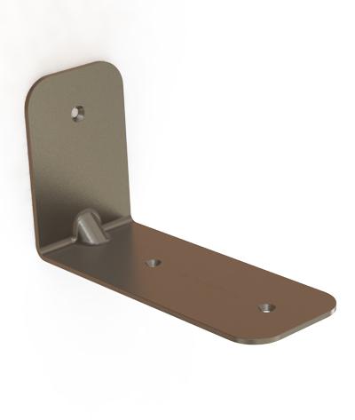
Figure 1b: This bracket has tighter tolerances than the part in Figure 1a. As a result, it probably will require advanced metal fabricating equipment to produce.
From the estimator’s point of view, the RFQ must include the quantity, part number and revision, requested delivery date, and preferred method of delivery. Again, we task customer service with enforcing that policy.
The RFQ also might include payment terms. This matters to the estimator only to the extent that company policy dictates the terms that will be offered to the customer, not the other way around. If a discrepancy between what the customer requests and what can be offered emerges, customer service is tasked with resolving the issue.The estimator’s role is to pay attention to detail and help customer service to perform brilliantly. Keep in mind that the specifics of the relationship between customer service and estimating are a matter of your company’s policy and practice.
In preparing a well-thought-out price quotation, customer service is going to pay attention to the buyer’s forecasts for demand for this item. There are usually many ways to fabricate the same item. The estimator wants to select the best fabricating method to match the demand and schedule.
Now here’s a pop quiz. Prepare price estimates for the brackets shown in Figures 1a, 1b, and 1c.
PDF drawings with dimensions and 3-D CAD models are available upon request.
At first glance, the brackets have several features in common: a basic L shape made from bent metal, three holes, and chamfered edges around those holes—also known as countersinks for flat-head screws.
Figure 1a is something that could be produced by a do-it-yourselfer. The countersunk holes are created with a drill point. The raw material is flat barstock. No plating or painting is required.
Figure 1b is similar to Figure 1a, but it is dimensioned with relatively tight tolerances. This part is more suited for fabrication with CNC turret press and press brake technology. The countersunk holes can be produced in a stamping press or by machining with a drill press or mill. The length of the flange and the stiffening gusset in the bend might prevent this part from being formed in the turret press. A press brake is probably required after the part is profiled to size. The drawing for Figure 1b specifies nickel plating.
Figure 1c shows a part that was designed with minimum material weight as the primary consideration. The material is precoated before stamping. Tooling will be the primary cost driver for this part. The estimate for the part shown in Figure 1c will be focused mostly on tooling design and fabrication. Once the tooling is completed, the cost of production entails the power to run the stamping press and the cost of the material feeding the press. The job will run with practically no labor input.
The dimensions for the part are only one element of the information needed before an estimate can be produced in detail. As mentioned before, we also need to know the quantity and the delivery schedule. Collecting this information as part of the RFQ is a routine customer service task.
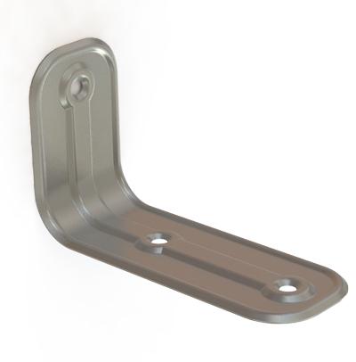
Figure 1c: This bracket has features that can be created only with the use of tooling in a stamping press.
For the purposes of this pop quiz, let’s use a batch size of 10 and the soonest delivery date that we can guarantee. The customer cannot wait more than 10 working days.
That delivery-in-days requirement puts the design shown in Figure 1c beyond the capability of our shop. The design and cost estimate for the tooling alone is likely to take more time than the manufacturing schedule allows. There is no apparent reason to proceed with process identification for manufacturing the design in Figure 1c. We are seriously considering a no-bid for that one.
Moving to the design shown in Figure 1b, let’s take a stab at process identification. A routine—albeit hypothetical—production plan allows three days for CNC programming and first article signoff, two days for staging of raw material, and two days through each production step. The part shown in Figure 1b could be manufactured with a sequence such as shear, punch, countersink, deburr, form, plate, and final packaging. That amounts to seven productions steps, which translates into 14 working days plus five days, first lot, nonrecurring expense—19 days earliest delivery ARO (after receipt of order). We are not going to order material or schedule machinery until we have a contract with the customer.
As with Figure 1c, because we cannot satisfy a major requirement of the RFQ, we probably should no-bid this project. However, we could finish the quote and deliver it to the customer with the explanation that we can do the job only if the customer can wait 19 days.
Last, we stare at Figure 1a. Considering process identification, Figure 1a could be manufactured with a hack saw, vise, and hand drill with a couple of drill bits. We’d get extra credit for using a hand file to knock down the edges. For this do-it-yourself project, the main lead-time is for raw material, and that’s available next day from a supply house. No plating is required, so from a first pass can-do filter, Figure 1a might be possible in terms of schedule.
Next, job compatibility with the shop needs to be examined. For the sake of discussion, let’s consider three shops that are equipped much differently from each other. One shop operates progressive-die stamping lines. The shop routinely engages in tooling design, manufacturing, and maintenance and is experienced in quick-change setup and in-process quality control. Such a shop would welcome the design shown in Figure 1c. However, it would not bid on designs like 1a and 1b because the work is not compatible with its core business mission. Unless the customer needs large quantities of product, stamping lines represent a significant amount of overhead expense.
The second job shop is equipped with a state-of-the-art CNC turret press. This punching machine can form flanges up to 50 mm long, about 1.96 in. That’s too bad. Our designs are all too long-legged for complete in-the-blank processing. This shop can stamp the countersinks with the turret, so it would just punch, deburr, form, plate, and package. Such a job shop probably would no-bid the design shown in Figure 1c because purchasing tooling for a single design doesn’t make sense. Turret press shops like tooling that can be used for a variety of projects.
The third and final job shop is a prototype shop. Its business mission focuses on small batch sizes and quick-turn projects. Function is the primary quality control criteria. The dimensions on the drawing are treated as inspiration. The staff in this prototype shop could produce a part like that shown in Figure 1c, but it would be produced entirely by hand using a variety of hammers and jewelers’ anvils and would likely take months to complete. The design in Figure 1a is well-suited to the prototype shop.
To recap our estimator’s glance at Figures 1a, 1b, and 1c, we have matched one design to one production facility with the appropriate capability and business mission. This was a demonstration of how an estimator can quickly sort out the incoming RFQs and focus on the best fit with the shop.
To continue the work on answering the pop quiz, let’s suppose that we work as estimators in the prototype shop. We’re making that supposition because if we were working in either of the other two types of shops, our example RFQ would lead us to no-bids and an abrupt end to the article.
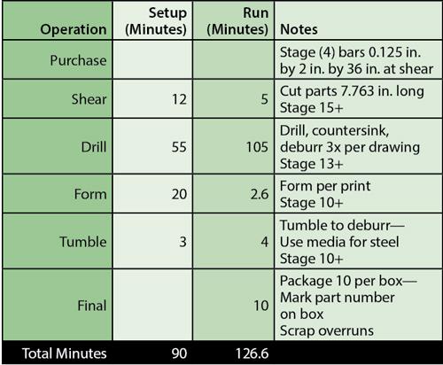
Figure 2: The total production time needed for the job is a little over 3.5 hours.
Our first-pass review of the RFQ hinted at the low-tech manufacturing requirements for the project. That does not mean that our shop must use a hack saw to part off the blanks. We could use an available ironworker and shear the blanks, as an example. There are a lot of options. To settle on a manufacturing plan, now is the time to prepare our estimator’s version of a work order to produce a batch of 10 of the parts shown in Figure 1a.
Our general plan for building a batch of Figure 1a parts is to cut some flat blanks, drill the holes, and then bend the parts. In order to decide how to cut the blanks, let’s figure out the flat blank size. The CAD drawing shows bilateral tolerances on the lengths of the legs (e.g., + 0.25/-0.50 in.). Those tolerances are well within the capability of our forming machine, so we’ll keep it simple and just add 5 in. + 3 in. = 8 in. flat before setback.
When the material bends it will stretch, so we need a setback amount in the flat to compensate for that stretching. Our shop standard for this material and radius is a -0.237-in. bend deduction, so our flat blank length is 7.763 in. For general material planning we can round that up to 8 in.
We’re going to need at least one setup piece, so we need at least 11 of the 8-in. workpieces, which is 88 in. of material. That 88 in. doesn’t really allow for kerf or clamping waste. A standard bar is a random 16 feet in length. A random 16-ft. length is approximately 192 in. long, so we need less than one full stick of stock bar of material for this job. We don’t have any in our inventory.
To make the fast delivery, we must hurry up the procurement of material. To control cost, we will keep the shipping length to 3 ft. We can get four parts out of a 36-in. length (4 x 7.763 in. = 31.052 in.), leaving almost 5 in. for clamping and squaring.
We need to start with at least three 0.125- by 2- by 36-in. bars. In an ideal world that will give us 12 parts, and we need only 10. How lucky do you feel? Are two setup parts enough for this? We have to set up three machines—shear, drill, and brake. Let’s add another raw bar to the plan for safety.Our first manufacturing step will be to stage those four bars at the shear for cutting to the 7.763-in. length. We estimate that it will take about 12 minutes to set up the shear and that we’ll lose one part as scrap. The shearing of the 16 parts will actually take 20 machine cycles—one trim cut to square the raw bar, then four more cuts to finish the bar. Each machine cycle takes 15 seconds. Twenty machine cycles multiplied by 15 seconds comes to 300 seconds of production time. To convert seconds to minutes, divide by 60 to get 5 minutes of run-time.
The next manufacturing step is to make the holes in the parts. Each part has three holes. The drawing shows a 118-degree drill point countersink, but our customer service agent has verified that the customer wants a standard 82-degree countersink for a #10 screw.
We’ll use a #2 drill in the drill press for the through-hole and an 82-degree Weldon® to countersink the holes. The setup on the drill press will require a back stop and a side stop and that setup changes two times for the other holes. We’ll allow 15 minutes for each setup, resulting in 45 minutes total for drilling. Setting up the countersink is just a matter of setting the depth stop on the drill press. No side or back stop is required. We’ll allow 10 minutes to set up the countersink.
Each drilling operation will take about 120 seconds. Each countersinking operation will take about 20 seconds. We expect to start 15 parts, and we will have one setup scrap part from the shearing operation to play with. The total time per part is 120 seconds to drill plus 20 seconds to countersink, resulting in 140 seconds. Multiply that by 3 holes to get 420 seconds for three countersunk holes in one part.
We have 15 parts to run. Multiplying 15 by 420 seconds gives us 6,300 seconds, or 105 minutes, for drilling. We expect to lose two parts during the drilling operation, so we’ll be staging 13 good blanks and three odd setup scrap bits to the next operation.
A note on the drawing states “Remove sharp edges.” We could do that next by using a sanding machine to deburr the flat blanks, or we could bend the parts and then toss them into the vibratory tumbler for ceramic media abrasion. Because we really don’t expect much burr from either the shear or drilling operation, let’s proceed with bending and later with deburring.
To form this part we are going to use a hand-operated leaf brake. Setup takes about 20 minutes, and each bending operation will take 12 seconds. We’ll bend 13 parts and expect to lose three to scrap, giving us exactly the 10 parts we need for the RFQ. (13 parts x 12 seconds = 156 seconds, or 2.6 minutes, for forming.)The deburring operation requires that the tumbler be set up with the correct media—either for ferrous or nonferrous work. This operation averages a 3-minute setup and about 4 minutes to load and unload and rinse the parts.
Last, we pack and fill out paperwork. The plan is to measure the parts to verify that they match the drawing and that the finish and material condition are satisfactory. We then wrap and box the parts for delivery. Ten minutes will be our budget for a batch of 10 of these little L brackets.
Because we are a lean and mean prototype shop, we use a flat shop rate of $90 per hour for estimating. From the work plan (see Figure 2) we see that we have 216.6 minutes of work, which translates into 3.61 hours. We multiply that by the shop rate of $90 per hour to get $324.90 for labor.
The material was $10.45 per 3-ft. length. We need four of those and have to pay freight. Our material cost for the estimate is $48. We can get it in three days for sure. We need some profit, so we are going to mark up the material by 50 percent. That leaves us with $72 as our material estimate.
Can we meet the delivery schedule? Even though it will take less than four hours to do the work, staging the work-in-process will add some time to the schedule. We can’t know for certain what the future holds, but we can anticipate a one-day delay between operations. We’re still OK—five days for staging and three days to get material.
As estimators, we have determined our labor cost at $324.90, and our material cost at $72 for a total of $396.90 or $3.97 per part in batches of 10 delivered 10 days ARO. We are quoting this with a deviation from the drawing by substituting 0.221-in.-diameter holes that are countersunk 82 degrees by 0.306 diameter for the 118-degree chamfers shown on the drawing. We pass that information on to customer service.
Customer service will, in turn, verify that the customer satisfies the accounting and other contractual terms to qualify them to receive a price quote from us. Customer service will format the data and present it to the customer.
Gerald would love to have you send him your comments and questions. You are not alone, and the problems you face often are shared by others. Share the grief, and perhaps we will all share in the joy of finding answers. Please send your questions and comments to dand@thefabricator.com.


The Fabricator is North America's leading magazine for the metal forming and fabricating industry. The magazine delivers the news, technical articles, and case histories that enable fabricators to do their jobs more efficiently. The Fabricator has served the industry since 1970.
start your free subscription
Easily access valuable industry resources now with full access to the digital edition of The Fabricator.

Easily access valuable industry resources now with full access to the digital edition of The Welder.

Easily access valuable industry resources now with full access to the digital edition of The Tube and Pipe Journal.

Easily access valuable industry resources now with full access to the digital edition of The Fabricator en Español.
In this episode of The Fabricator Podcast, Caleb Chamberlain, co-founder and CEO of OSH Cut, discusses his company’s...


