


Contributing Writer
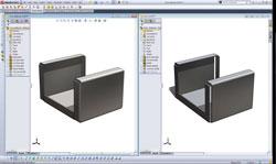
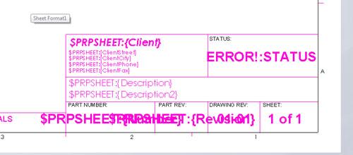
Figure 1: Two modeling techniques are compared. Which model would you rather build?
Every operator of a 3-D CAD workstation is involved in a workflow—probably several workflows, truthfully. Also, depending on the deliverable, the workflow of a 3-D part model differs from that involving the production of a 2-D manufacturing drawing.
So here’s a prediction: A person’s first experience using 3-D CAD immediately will result in a workflow. That process probably will be focused on scanning through menus, looking for things that seem like they might do something desirable. This workflow is the result of mental vision of the desired result but lack of knowledge of the needed terminology and technique.
With each modeling session, the CAD jockey’s workflow will become less dependent on searching for methods and techniques. Instead, it becomes more a repetition of what worked last time. To some extent, the productivity of the CAD jockey automatically increases with experience. Once the CAD menu is memorized, the mouse clicks and keystrokes just happen faster. Here’s another prediction: This emerging skill set of CAD techniques will stagnate until something goes wrong.
Everything goes wrong initially, and as techniques are being mastered, very little productive work is being performed. Sometimes the same model is remodeled repeatedly from scratch simply to take advantage of some “new” CAD ability.
The blessing and curse of 3-D CAD is that many paths lead to the same result. Figure 1 shows two models of the same part side by side. Both models are the same size and are shown before the welding and grinding that closes all seams.
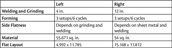
From the table in Figure 2, we conclude that the left-hand model makes better use of sheet metal and is easier to weld. The right-hand model may have some slight advantages, but it generally looks like a rookie’s design.
Based on years of observation, I believe that after the completion of about 30 production 3-D models and related documentation, the CAD jockey’s workflow could be described as established and is acceptably predictable.
Before venturing farther, we need to pause here and realize that, although the CAD workflow may be established and functional, it also may be less than optimal. At a minimum, the CAD jockey is not fully using all of the software’s functionality. Most likely the workflow does not incorporate enough downstream vision, such as model utilization in other projects, ease of revision, and compatibility with purchasing or IT departments. Almost certainly the current workflow will incorporate needless redundant labor.
There is a point of diminishing return, however. Spending a day to save 10 minutes may not be an example of good effort. On the other hand, if a crew of several CAD operators save those 10 minutes every day, the payback is obvious.
So avoid focusing too much attention on CAD elegance and not enough attention on getting the work done. The “perfect” workflow is a transient event.
The acceptable workflow tends to stagnate unless pressure forces change. My recommended source of prudent workflow change is found within one’s self. The proficient CAD jockey reads the help FAQs; attends user group meetings, such as the SolidWorks® User Group Network (www.swugn.org); participates in online discussion forums; attends value-added reseller courses and events; goes to tradeshows like SolidWorks World; and happily mentors newbies. Learning never ends.
Typically, however, the pressure to change the workflow comes externally in the form of product design revision. Obsolescence, market demand, and product performance have their perpetual impact on CAD workflow.
The task to change an established model in a specific way forces the CAD jockey to evaluate the consequences of the modeling techniques that were used. Those techniques that prove to be easy to edit within the constraints of the overall manufacturing process will be incorporated to improve the future CAD workflow. However, some CAD modeling techniques are very difficult to edit.
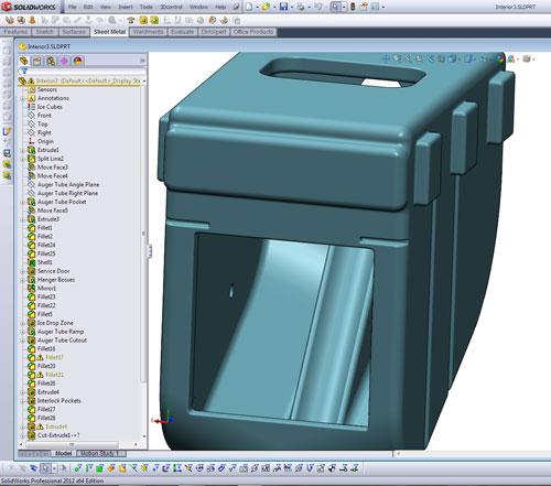
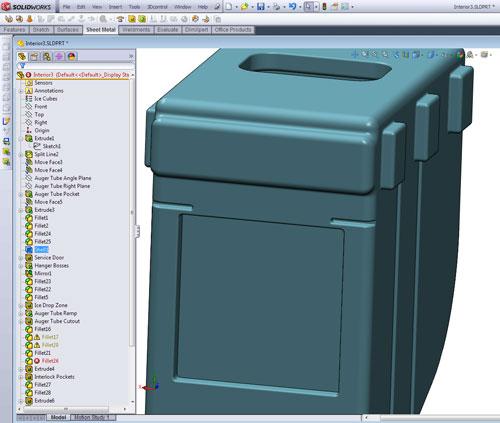
Figure 3a and Figure 3b show a slightly complex model before and after a simple edit. In Figure 3a we see a through-window cut in a wall and are looking at a trough inside the box. I changed the shelled wall thickness from 2 in. to 2.5 in. The result is shown in Figure 3b. Numerous features have failed. It is going to take some serious CAD labor to change this model successfully because of the CAD techniques that were used originally. With this in mind, our plan is to purge the rookie mistakes and improve the CAD workflow.
There is a skill to winnowing CAD modeling techniques. Difficult-to-edit features might include things like derived sketches that have intrinsic protection against accidental edits. We used such a feature in last month’s article (“3-D CAD: Handling imported data during sheet metal design,” Precision Matters, The FABRICATOR, October 2012, p. 64) to ensure that all of our rips were the same size. When deciding whether or not a derived sketch is a good thing, we must understand the overall design intent. When faced with the dilemma, it is best to consult with colleagues and agree on future steps. Having a suite of policies on CAD techniques, including derived sketches, external links, virtual parts, and file name conventions, is an important element of a well-mannered workflow.
As a workcell in the business process, the CAD function addresses invention, design, engineering, documentation, and revision management. Each of those functions has a unique CAD workflow, and many of those workflows use conflicting CAD techniques.
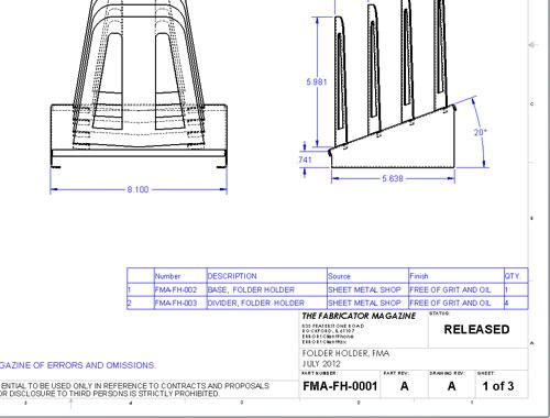
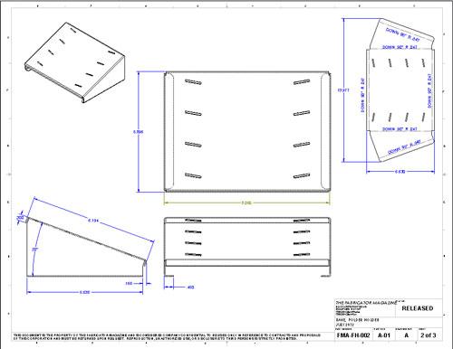
A seasoned CAD jockey adapts the workflow to the task at hand. Figure 4 shows a sheet metal chassis that was quickly modeled. No bends are shown, and no indications are given as to how the part will be built. It does show the functional surfaces of the part, and it works great for quick development and exploration.
Invention requires speedy modeling. In this particular mode, a CAD operator isn’t worrying about rebuild times, drafting standards, or manufacturability. Parametric links are necessary and useful; file names are arbitrary. The only real standard is speed—a need to visualize the product’s design quickly.
My recommendation is that if you can extrude faster than you can revolve, then extrude. But in your training time, develop the speed skill to revolve, so you can select a technique when it makes optimal sense. Fond readers of this column may recall that revolves are kinder to the CPU than extrudes.
Final release of a product to manufacturing may not tolerate the CAD techniques that were required for invention and initial product visualization. Consider a parametric link between a screw and a chassis. The chassis has a hole that follows the screw’s position in the assembly. It is wonderful to be able to keep the hole and the screw together while stretching and pulling the design during the product development modeling sessions. Once the design is committed to manufacturing, the hole should no longer be linked to the location of the screw. In the production CAD model, the location of the screw should be driven by the hole’s location.
Now let’s put the apparent workflow conflict in a different light: The designer cares about where the screw is, while the fabricator cares about where the hole is. Sometimes the designer and the fabricator are the same CAD jockey, just at different moments of the day.
That kind of insight into the various kinds of CAD deliverables and related workflows may change the way the CAD jockey approaches a task. It is a rookie mistake to enter a brainstorming session with fabrication as the only priority. Exploration and discovery are higher priorities at the early stage of the product’s CAD evolution.
Once the design evolves from concept to planning, design for manufacturing enters into the selection of modeling techniques. Quick blobs give way to realism and detail. The persistence of CAD techniques like parametric links that may be used in this middle stage of product design remain responsive to changes, but not to the same extent as can be accommodated during the first stage of modeling. Detail and specification bring inertia that impedes design revision.
The CAD department has standards for preparation of final documentation and models. Such standards apply later in the product’s design life. Perhaps one element of that standard for final models specifies that all modeled features be renamed with meaningful titles and descriptions. For example, Cut-Extrude19 gets renamed as Trigger Axle Pocket. That plain language policy is rational for models of parts that are in production. In future years, the CAD jockeys that revise the model will benefit from the clarity in the documentation that is built into the model’s history.
Such diligence about feature names is a complete waste of time for models that are as likely as not to be deleted in the next few minutes. Brainstorming sessions do not benefit from detailed policy and procedure. Manufacturing does not benefit from a fragile and poorly administered CAD database. Thus, we see the need for optimized workflows that anticipate hand-off as the product moves from concept to prototype to production and maintenance.
Frequent readers of this column may recall editions that delved into the setup of the CAD workstation for optimal workflow:
The tips and techniques discussed so far apply at even the most entry-level CAD. As a side note, SolidWorks includes a Design Checker tool that can be tailored to verify fonts, notes, view settings, materials, and other details related to your business rules. The 3-D CAD software I’m using is licensed in packages that have increasing levels of capability and cost. We also have looked at a few of the accessory tools that are not part of the basic license—sheet metal costing and mechanical load/strain simulation in particular. The goal of that shallow exploration of software tools is to alert you to the wide scope of solutions for sale that address specific CAD workflow issues.
A CAD Workflow Example
With all of that said and in place, we now set up an example CAD task scenario. Our mission, should we decide to accept it, is to produce a manufacturing drawing for a sheet metal part. Our final drawing is to detail both the flat and folded conditions of the part. The model for the part is given to us as a STEP file. Here’s our step-by-step CAD workflow:
Excluding Step 8, such a 9-step workflow could be routinely completed in less than five minutes. Adding dimensions and special notes to a drawing is an artistic endeavor and might take another 15 minutes for a typical sheet metal part.
It will be fun to read this article 10 years from now to see what inflation has done to time, but 20 minutes to make a fabricator’s drawing isn’t too bad.
Gerald would love to have you send him your comments and questions. You are not alone, and the problems you face often are shared by others. Share the grief, and perhaps we will all share in the joy of finding answers. Please send your questions and comments to dand@thefabricator.com.


The Fabricator is North America's leading magazine for the metal forming and fabricating industry. The magazine delivers the news, technical articles, and case histories that enable fabricators to do their jobs more efficiently. The Fabricator has served the industry since 1970.
start your free subscription
Easily access valuable industry resources now with full access to the digital edition of The Fabricator.

Easily access valuable industry resources now with full access to the digital edition of The Welder.

Easily access valuable industry resources now with full access to the digital edition of The Tube and Pipe Journal.

Easily access valuable industry resources now with full access to the digital edition of The Fabricator en Español.
In this episode of The Fabricator Podcast, Caleb Chamberlain, co-founder and CEO of OSH Cut, discusses his company’s...


