


Contributing Writer
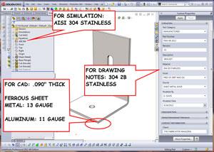
Figure 1a: This sheet metal bracket has custom properties for drawing notes and material assigned for simulation.
When designing a product using a CAD workstation, the CAD jockey could benefit from having a reasonable knowledge of:
As an example of a design optimizing work flow, consider the bracket shown in Figure 1a. Our design goal is to model a bracket to support a 100-lb. load. The bracket shown in the graphics window in the center of the screen shot in Figure 1a is the starting point for our design concept. Note that the part is modeled as bare, 13-ga. 304 stainless steel.
The Custom Property form to the right of the graphics window displays the part number, revision, and other custom properties. Even though it may look like the material, 304 2B stainless, is defined in this form, it is not. The material description appears in the 2-D drawing for this part. For simulation of mass and center of gravity, the material needs to be set in the Feature Manager to the left of the graphics window. In Figure 1a the material has been set to AISI 304. A CAD jockey can change the material in a third place, but only for the purposes of cost analysis.
Figure 1b shows the sheet metal costing tool. Two control panels exist for this tool. To the left of the graphics window is the Sheet Metal Costing Manager. It shows in detail the costs for setup, cutting, bending, and other features and operations that contribute to the total cost. As needed, we can add or eliminate operations using this. We also could manually enter prices for any of the operations to override the defaults from the Costing Template.
To the right of the graphics window is the Sheet Metal Costing Panel. The comparison section of this costing panel shows the previous cost and the current cost. Both of these costs are estimated at $3.59 in Figure 1b, based on a batch size of 25 parts. We have some confidence in this costing estimate because we consulted previously with our manufacturing department for costs associated with laser cutting, bending, and material before we set up our Costing Template.
If the prices set in this template are incorrect, then the calculated costs could be misleading. Our goal is not to produce a price quote for purchasing, but to optimize a design. We need a reasonably close price reference for evaluating alternative designs. Given the constant fluctuation in the currency value, we may need to update the Costing Template several times during the year to keep the calculated cost from drifting too far from the real world.
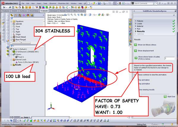
Perhaps before looking at cost, we should evaluate this design to see if it meets our structural requirements. Will this bracket support a 100-lb. load? To get an answer to that question, we can look at Figure 2a, which shows the result of running the Simulation Express Analysis Wizard. Blue means it probably is OK; red means it likely needs correction. During the Simulation Express Analysis Wizard setup, we declared the long flange of the bracket to be fixed or stationary. This is indicated by the little green force vectors that are scattered along the vertical flange.
We then applied a 100-lb. load to the short flange of the bracket, indicated by the little red force vectors. The wizard can animate the distortion of the bracket caused by load, show where the greatest stresses are, or highlight the areas where the bracket will fail under load. The latter is the option selected for the display in Figure 2a.
Note that the express version of the simulation tool locks entire faces when defining fixtures or loads; the full premium license is required if you need to analyze fixtures and loads that represent bolt head clamping. The Simulation Express tool still gives useful estimates of strength—particularly for basic designs like this example. We’ll just have to keep in mind that this strength analysis is based on slightly unrealistic load and clamping.
As we glance at the Graphics Window in Figure 2a, we see some areas along the bend that are highlighted in red. The wizard has determined that these areas have a factor of safety (FOS) less than 1. If you’re not familiar with FOS, it is calculated by dividing strength by load. If the FOS is 1 or greater, you have more strength than load—probably safe. If the FOS is less than 1, then you have more load than strength—probably not safe.
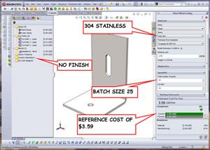
Figure 1b: A reference cost is calculated based on material, features, and batch size.
With a large FOS, you might have more safety, but you also have excessive strength, which translates into more material and cost. Without consideration of other design objectives, our general plan is to keep the FOS between 1 and 2.
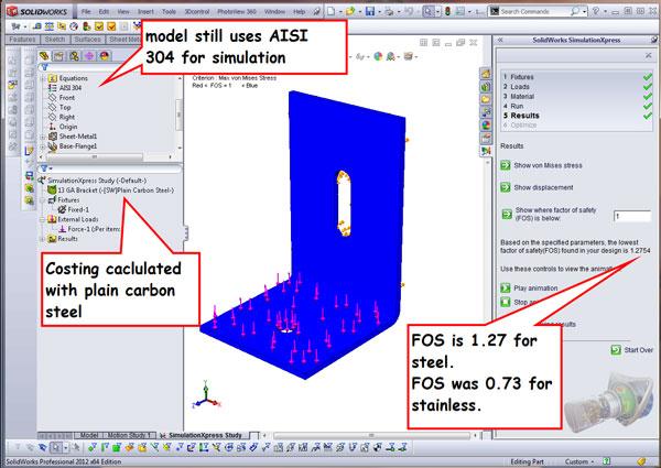
The wizard is reporting an FOS of 0.739205. What can we do to improve it? Either reduce the load or increase the strength. One way to stiffen this part without changing any dimensions is to change the alloy. What happens if we change from stainless steel to plain carbon steel? As shown in Figure 2b, the FOS goes up to 1.27, which indicates that we have satisfied our design goal of supporting a 100-lb. load.
The Sheet Metal Costing Panel setup shown in Figure 3a is nearly identical to that of Figure 1b—no finish, batch of 25—except that the material was 304 stainless and now is plain carbon steel. This change has been made only in the costing panel. We haven’t changed the material attached to the CAD model yet. As suggested earlier, once we settle on a material for costing and strength considerations, we can set it in the Feature Manager so the mass properties of the model—weight and center of gravity—are correct.
Note the cost comparison in Figure 3a: The steel price is lower than the stainless steel price. This is related to the cutting process; laser cutting stainless steel with nitrogen assist gas is more costly than cutting steel with oxygen. It also is because of the lower cost per pound for the raw material. In Figure 3a, the steel material cost is shown at 12 percent of the total cost. In Figure 1b, the stainless material cost is 19 percent of the total cost.
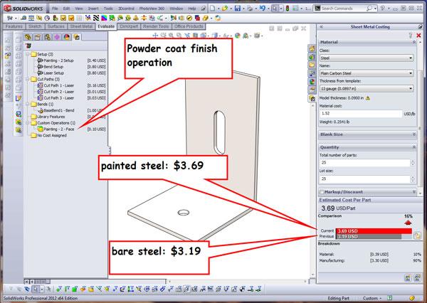
However, we will need a coating to prevent the steel bracket from rusting. What happens to the cost if we powder-coat this part? Figure 3b answers that question. In the Sheet Metal Costing Manager—to the left of the graphics window in Figure 3b—a custom operation was added to paint the part. The cost comparison shows that a painted part costs more—$3.69 versus $3.19—than a bare steel bracket.
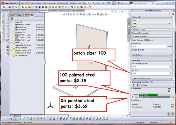
How can we lower the cost of the part? There are innumerable possibilities, but one that jumps to mind is to increase the build quantity. In Figure 3c, we see that the same bracket costs less if you buy more—$2.19 each in batches of 100, going up to $3.69 each in batches of 25. This mostly is due to the setup costs, which are amortized over the batch size.
If you’re not familiar with setup costs, setup is the amount of time it takes to prepare a machine for operation. The Costing Template retains your settings for the processes you might use in your costing analysis. These settings include the cost for setup and the names and speeds for processes like cutting and bending.
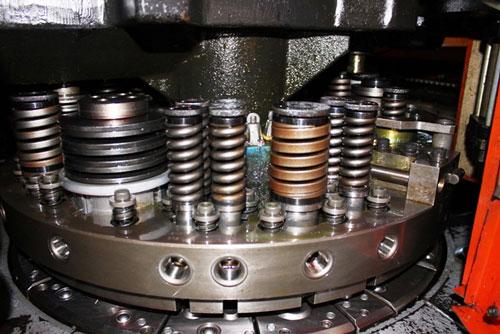
Let’s compare a CNC turret punching machine to a laser cutting machine and see what makes the most sense for cutting out these flat patterns from sheet metal. The CNC means that a computer program is positioning the workpiece, rotating the turret to select the correct punch, and then pressing the punch through the workpiece to eject a slug through the die. The turret refers to the way the machine holds the tooling. A round turret several feet in diameter holds between a dozen and several dozen sets of punches and dies (see Figure 4). Setting up the turret for operation takes labor; for cost-optimizing purposes, one hour to set up a turret is a good average.
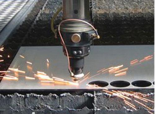
A laser cutting machine (see Figure 5) also uses a CNC program to position the workpiece, turn on the beam to peck and pierce through the blank, and then guide the beam through the workpiece to complete the cut path. Unlike the CNC turret, there is only one tool, and it always is loaded. An operator is needed to set up the assist gas manifold and clean out the spark box. One-half hour is a generous estimate for laser setup for a batch of parts.
The nuances in the tradeoffs between stroke-based machinery like a turret press and a slicer like a laser are likely to require expert analysis by professional cost estimators.
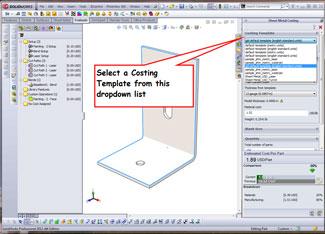
Figure 6: Selecting a Costing Template is easy to do. Which template is the right one? Answers revealed to many questions next month.
By itself, the setup time does not make running the laser less expensive than a turret punch. The laser starts up easy and can cut a variety of shapes very quickly. The turret takes longer to set up, but it can outperform a laser on applications that require repeated actions, such as punching out several same-sized holes.
The turret also makes burrs that almost certainly have to be removed mechanically from the finished part. If you want burr-free parts, deburring is an additional process required after punching.
The laser will produce dross instead of burrs, but it may be so minimal that it won’t require secondary grinding or sanding. The laser cutting machine, however, creates a heat-affected zone around the laser-cut parts. For some aerospace products, this can eliminate the laser process from consideration as a cutting tool of choice.
The turret requires precision-hardened tooling, a significant capital investment tailored to produce a specific cutout. The laser has a resonator and optical path, which both wear out and require service, but do not demand the frequent attention that a turret press demands.
If you are in the manufacturing trade, you know that lasers and turrets have other exclusive advantages and drawbacks. If you are in the design trade, this discussion may already have tested your interest. My purpose was to illustrate how costs are driven by process. The manufacturing process may be very specific to an individual batch of parts. As a designer, you may not have any control over whether your product is laser-cut or stamped.
The Sheet Metal Costing Panel makes it easy to select a manufacturing template from a dropdown list, as shown in Figure 6. You could have templates set up for laser, punch, waterjet, or saw. However, I am recommending to those in the design trade to set up a generic cutting process and use it as a base line for cost comparison. Cost optimizers—people primarily involved in design decisions—probably need only to specify that the part be cut, not how the part be cut.
If you are certain that you need to compare the difference in cutting methods, then you will need more detail in your costing template. That will be addressed next month.
As a work flow or labor of CAD, cost optimizing relies heavily on relative improvement in cost derived from design changes. The costing tool is using the CAD model, a schedule of prices, and conversion formulas to report the costs it can identify.
The driving element for the calculated cost is the inventory of features to be produced—holes, pockets, cutouts, and profile. The CAD model provides that data effortlessly.
The sheet metal costing tool tries to be as automatic as it can but needs help in identifying unmodeled operations like painting, plating, and screen printing. If your design calls for those processes, then you must use the Sheet Metal Costing Manager to add them into the operation list to be included in the cost comparison calculation.
The Sheet Metal Costing Manager also reports features to which no cost has been assigned. This happens because the system must match the material thickness and the process to the feature. If the costing template is missing a process or a material, then the feature ends up in the no-cost-assigned folder.
These no-cost-assigned features can be handled several ways:
The structural analysis gives a prediction of how the physical model will perform. The prediction of cost, like the prediction of strength, is data-driven. The better the data you supply, the better the predictive value of the simulation.
Gerald would love to have you send him your comments and questions. You are not alone, and the problems you face often are shared by others. Share the grief, and perhaps we will all share in the joy of finding answers. Please send your questions and comments to dand@thefabricator.com.


The Fabricator is North America's leading magazine for the metal forming and fabricating industry. The magazine delivers the news, technical articles, and case histories that enable fabricators to do their jobs more efficiently. The Fabricator has served the industry since 1970.
start your free subscription
Easily access valuable industry resources now with full access to the digital edition of The Fabricator.

Easily access valuable industry resources now with full access to the digital edition of The Welder.

Easily access valuable industry resources now with full access to the digital edition of The Tube and Pipe Journal.

Easily access valuable industry resources now with full access to the digital edition of The Fabricator en Español.
In this episode of The Fabricator Podcast, Caleb Chamberlain, co-founder and CEO of OSH Cut, discusses his company’s...


