


Contributing Writer
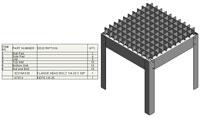
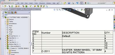
Figure 1: After inserting the default BOM table, we see many data entry errors and omissions.
In the previous column we discussed the notion that a bill of materials (BOM) table is just a way to present data entry results. Somebody has to type in the information that is displayed. Otherwise, you get results similar to those shown in Figure 1—bum part numbers and descriptions.
As CAD jockeys, we are particularly interested in minimizing the tedium of that data entry process. One way to do that is to set up the CAD workstation with data entry forms—see Figure 2—and templates to optimize our work flow.
As part of this effort, our design of data entry forms, table templates, and CAD admin procedures will benefit from understanding how the information in a BOM is stored and retrieved.Some of the verbiage used in the discussion of CAD modeling in this column is unique to the software I’m using. However, you will find that other software offers similar functionality in most instances, even if wording and commands are different than those mentioned here.
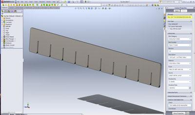
Our cutting table project has produced an assembly with several components—legs, sides, and slats. All of these components are simple sheet metal parts. Now we might add casters. Our caster model will be an assembly of a wheel, axle, and caster housing. We can put multiple copies of the caster assembly into our cutting table assembly.
To be clear about terminology, a component refers to an item found in an assembly. A component can be another assembly or simply a part. An assembly exists in our storage system as a file with a name and a specific type of file extension—sldasm. That assembly file contains pointers to the file names of the components in that assembly. A part also exists as a file with a name but a different file extension—sldprt.
Parts do not contain other parts; that is what assemblies do. Parts may have multiple bodies as features, but those bodies don’t show up as separate items in the BOM table. What can make BOM tables more complex is the fact that any component may have multiple configurations.
BOM table functionality includes options for each column to determine what will appear in that column of the table. One of those powerful options is to use file properties to store and retrieve data. We can use file properties for other tasks too—part marking, equations, title blocks, and notes, to mention a few.
The Windows® operating system manages the storage and retrieval of file properties. If you master the elemental File>Properties user interface, you don’t need to know much else that follows here. But read on to learn a bit about alternative methods for entering data for the production of great BOM tables.
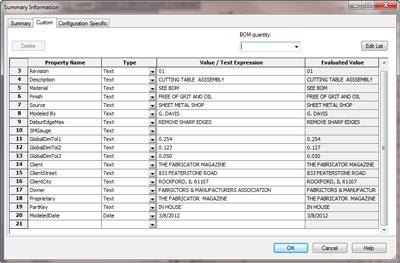
To experience why I am such a fan of alternative methods of data entry, open a component file. Then select File>Properties. This brings up a dialog with three tabs—Summary, Custom, and Configuration Specific (see Figure 3a). We’ll save the Summary Tab for a separate discussion in the future. The other two tabs, Custom and Configuration Specific, are of great interest right now.
We use the Configuration Specific tab for models like bolts that have a common shape but many different sizes and corresponding descriptions and part numbers. If the model comes only one way, we usually can get by with using just the Custom tab.
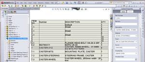
Figure 4a: An example of an indented BOM is shown. Note that item No. 7 is made from items 7.1, 7.2, and 7.3.
When you select either the Custom tab or the Configuration Specific tab, a table containing file properties is displayed. This is a fairly simple user interface: Click in a cell and type your data. The drop-down lists are generic and not very helpful. You can copy multiple rows and paste them into another model’s table, but it is tricky. I find that when I’m typing data, this user interface requires more concentration than I prefer.
File Properties—One for Each Configuration
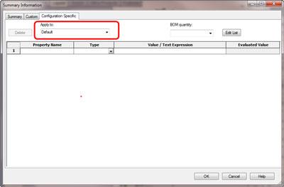
On the Configuration Specific tab, you have one more control that sets which configuration the table is displaying. In Figure 3b I’ve drawn a red rectangle around the control. Because a component can have as many configurations as you need, the drop-down selection list can be short.
In the Figure 3b example, we’re looking at the properties of the cutting table. It has only one configuration: Default. You will find no file properties defined in the Configuration Specific properties table so far.
You can have file properties with the same names; for example, Description can exist in both the Custom file properties table and on all of the Configuration Specific tables. The functionality built into BOM tables will try to display the data from the file property found on the Configuration Specific tab’s table first, and then it will look on the Custom tab. So, if a file property with the same name between Custom and Configuration exists, the BOM table will display the Configuration Specific value and ignore the Custom value. If the name of the file property is not found in any file property table, then the BOM table will display a blank. In the example of Figure 3a, we see that the Custom tab has a file property defined with the name Description, and it has a value set to Cutting Table Assembly.
Reminder: A component can be either a part or an assembly. The BOM table is retrieving data from the component’s file properties.
If the component is an assembly, then we have an assembly inside another assembly. At each layer of the nest—or at each component—a set of file properties can be found. The BOM table has options to allow you to control how to display the information from nested components:
Figure 4a shows an indented BOM table with detailed numbering. Note that item 7 is a caster and that there are four of them in the cutting table assembly. Items 7.1 through 7.3 are caster components—the mounting plate, steering frame, and wheel. Only one of each is found in each caster assembly.
Figure 4b shows the same BOM table set to display top level only. Notice that the details of the parts that make up the caster—item 7—are no longer displayed. There is no “right” choice in these BOM options. I’m sure that you’ll find situations where you need each of them.
Remember, if you create a new component from a template, that component will start out with default values from that template for all of its file properties. In other words, blank or garbage values will appear. If you copy a part and edit it to create a new part, the copy will start out with identical file properties too. If you dissolve a component that is an assembly, its components now become what the BOM table will retrieve data from.
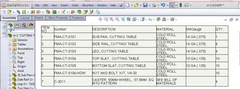
Figure 7: Compared to Figure 1, this BOM is better. It has more useful columns and more complete data entry.
As alluded to earlier, a BOM table is organized into columns and rows. Each row represents a component in the assembly. If nested subassemblies are included, the BOM table options can be set to indicate or hide the nesting relationship. Thus, the number of rows is determined by the number of components in the assembly, as well as the display options set for the BOM table.
You can sort the table to change the sequence in which components appear in the table, but the first time the BOM table is created, the components are listed in the same sequence in which they appear in the assembly’s Feature Manager. So the components appear in the order in which they were inserted into the assembly. An option which forces the table to follow the assembly order also can be used; this is generally my preferred setting.
The number of columns is left entirely up to you. There is no limit. Adding or deleting columns is just a right-mouse-click away.
Each column can be set to retrieve data from any of six sources. We’re not going to detail all of the possible sources. Once you’ve mastered one, the others are relatively minor variations.
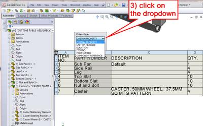
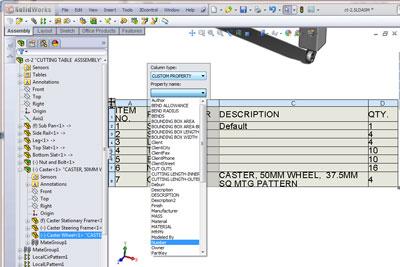
Click at the top of any column in a BOM table (see Figure 5a, Step 1). A pop-up menu will appear. Click on the Column Property icon (see Figure 5a, Step 2). A drop-down selection will appear at the top of the column (see Figure 5b, Step 3). The selection list offers any of seven things to display in the column: Custom Property, Unit of Measure, Equation, Item Number, Part Number, Component Reference, and Quantity. I recommend you check out the Help system for each of these column types. Component Reference can be very handy when documenting wire harnesses, for example. The built-in part number functionality might be something your firm would prefer over the Custom Property route that follows.
I’m particularly fond of Custom Property as a BOM column type. Such a column will retrieve data from a specified file property. In Figure 5c we have selected Custom Property from the drop-down list, and now we can select which file property to use. This is why I like this method: You can create any combination of file property names and values to populate your BOM tables. Part number and description are pretty obvious. You might want to include cost, bin stocking location, or any other information your heart desires.
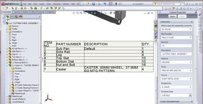
In Figure 5a, column B is supposed to be displaying part numbers, but it is displaying file names instead. So, I’ve decided to use my own custom property that I’ll name Number for that column. The result is shown in Figure 5d. Only item No. 7 has its number properly set. The other six components in the cutting table assembly still are missing some data entry.
Now that our BOM table has been customized to our liking, we are going to create a BOM template so we don’t have to fuss with column properties again. The process of setting up the template is a one-time event, or at least editing the template itself usually is done infrequently.
Creating a BOM template from a BOM table that you have created is just a right-mouse-click away. To begin, click anywhere in the table. A pop-up menu will appear (see Figure 6). Just select Save As and then fill in the file name and select a location to save the template.
The default template was used to create the BOM table embedded in the assembly shown in Figure 1. After reading that sentence carefully, you might say, “BOM tables are expected in drawings. Why put a BOM table in an assembly with other components?” I use a BOM table in my assembly as a preview of the data that will appear in the BOM table on the drawing. Tables in assemblies are easy to hide when they are distracting. You can even delete them once the data in the BOM is complete and accurate.
As we noted at the start of this article, the information displayed in Figure 1 is in need of improvement. The part numbers are incorrect, and many of the descriptions are blank. This sad state of affairs is rather common as a project progresses from initial concept to preparation for manufacturing.
In Figure 7 we see progress. The number column is now displaying valid part numbers—likewise with the descriptions. We’ve added columns to display material and sheet metal gauge.
Next month we’ll look at how that data entry was done. As a hint, I used a couple of different techniques. Using BOM tables to accomplish data entry is one way to do it. As good as that trick is, I usually prefer using forms created with the Property Tab Builder. That will allow us to almost completely bypass the File>Properties work flow (see the right-hand side of Figure 8). We’re looking forward to some useful tricks when designing data entry forms. Plus, we have a detailed discussion of part marking that really leverages our powerful file properties.
Gerald would love to have you send him your comments and questions. You are not alone, and the problems you face often are shared by others. Share the grief, and perhaps we will all share in the joy of finding answers. Please send your questions and comments to dand@thefabricator.com.
aceholder

The Fabricator is North America's leading magazine for the metal forming and fabricating industry. The magazine delivers the news, technical articles, and case histories that enable fabricators to do their jobs more efficiently. The Fabricator has served the industry since 1970.
start your free subscription
Easily access valuable industry resources now with full access to the digital edition of The Fabricator.

Easily access valuable industry resources now with full access to the digital edition of The Welder.

Easily access valuable industry resources now with full access to the digital edition of The Tube and Pipe Journal.

Easily access valuable industry resources now with full access to the digital edition of The Fabricator en Español.
In this episode of The Fabricator Podcast, Caleb Chamberlain, co-founder and CEO of OSH Cut, discusses his company’s...


