


Contributing Writer
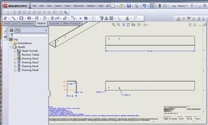
Figure 7e: The final step in making a shop drawing is to add dimensions.
As fabricators, our contribution to a project’s design and 3-D CAD modeling is frequently limited to minor adjustments to improve the manufacturability of the item. One of our business objectives is to transform a CAD file into a deliverable manufactured item with minimum overhead. It is worth noting that we are also experts in the various manufacturing processes we operate; we recognize excellent manufacturing drawings and know exactly what is needed on them.
Here’s an industry secret: Great shop drawings don’t always follow international drafting standards. For example, a shop drawing might include all dimensions required for forming a part for the benefit of press brake operators but substantially lack dimensions for all other features, the thought being that the holes and other features were produced with precision CNC technology and need not be inspected by humans. The point is that your organization can produce drawings for internal use that omit details that would be required on drawings intended for external distribution.
The design and engineering team that produced the CAD model might also be able to produce the manufacturing drawings. The incentives for doing so include the ability to support competitive bidding, tighter control over the documentation, and, of course, tradition. With a few iterations of communication and drawing updates between the teams, acceptable drawings are achievable, particularly if ASME Y14.41 standards are being followed to allow the maximum use of 3-D data and minimum reliance on traditional 2-D drawings.
Here’s an industry forecast: As virtual prototyping technology improves, the design team will be called on to focus more on product design, while the manufacturing department will be asked to concentrate on all things related to fabrication—especially the production of the 2-D manufacturing drawings.
In the March 2012 Precision Matters, we discussed some possible methods of filling out a bill of materials (BOM). Building on the theme of how good design work can influence the manufacturing process, let’s focus on creating the best possible model, which will accompany the BOM.
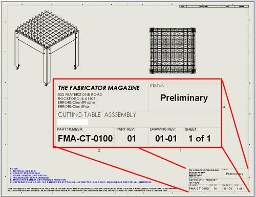
Figure 1 shows a design project for a cutting table. Regular readers of this column will recognize that this design has been evolving over the past several editions of Precision Matters. Because we designed this cutting table, we have full control over the model. By my declaration, the adjusting of the table’s size and shape has been completed and we’re ready to build it.
We are about to transition from designers to manufacturers. Let’s consider the several tasks involved in “releasing” the model for production:
Typically, the design team is heavily involved in preparing and approving that last bulleted item. It might include colors, textures, packaging, part marking, tolerances, and other details that are not apparent just by looking at the surface details of the 3-D CAD model.
In our example scenario, our manufacturing department is tasked with the production of the assembled table including all of the hardware. This will require the preparation of a BOM and an assembly instruction drawing. We will not make drawings for the off-the-shelf items like nuts and bolts. We will make drawings for all of the custom-fabricated components.
You can use one of several methods to lock the design and exchange files between design and manufacturing parties. The primary consideration in methodology is how to incorporate feedback. Will improvements made by the manufacturing staff in its 3-D model be implemented in the master design model that the design staff controls? If no feedback is required, then STEP file format is a convenient way to lock the design and still give manufacturing all the detail it needs.
On the other hand, if the goal is to adopt the model produced by manufacturing as the controlling design, then you’ll need to follow the dictates of the CAD software the team is using. I find using SolidWorks’ Pack and Go is a useful tool for producing a zip file that contains all of the required files for sharing in a native SolidWorks CAD database.
SolidWorks also offers a collaboration tool that allows you to create secure workspaces using Internet access for all team members. This online arrangement could prove more advantageous in numerous ways when compared to e-mail file sharing:
For this example, we are going to proceed as if we were a customer sending files one-way to a job shop for production. The plan is to export our design in STEP format and then “send” it to ourselves. When we “receive” the STEP files, we’ll import the models and create our BOM and drawings.
Exporting in SolidWorks is as easy as File>Save As and then selecting the desired file type. In this scenario, we will save our top-level assembly as file type STEP. This puts all of the components in the table into a single file. If we wanted to have only a single part per STEP file, we would have to open the part in a separate window and use File>Save As from there.
When the file is imported—using File> Open with a file type of STEP—we are prompted to select a template to use when creating the part or assembly. As with the Custom Properties form and the drawing template, we have created our own templates for assemblies and parts. These templates set the unit of measure and other default settings to our preference.
Please be cautious when importing the STEP file because SolidWorks will create models that default to the same file names as the original components. You probably will want to move the STEP file into a folder that is separate from the master design model so you don’t accidentally overwrite a design file with an imported dumb model. Imported STEP files arrive without any design history, which is part of the reason they are referred to as “dumb.” The absence of parametric links is also implied by the dumb moniker.
Every manufacturing department has rules and procedures; ours is no different. As a matter of policy, if we change any feature on the imported model, we must seek consent from the designer before building. We also have standards for our shop drawings. Figure 2 shows a close-up of the title block for our shop. Our shop’s drawing template defines the what and where of how the data appears in the title block. Our shop’s Custom Property Form—see Figure 3—makes it easy to perform the data entry.
You’ll note that the part number FMA-CT-0100 that is entered in the form in Figure 3 appears in the title block in Figure 2 because of the way our drawing template is designed. Our shop drawing template will work with any model that has had our Custom Properties form applied to it, because we designed the data entry form, using the Property Tab Builder tool, and the drawing template to work with each other.
The procedure that our hypothetical manufacturing department follows with newly received STEP files is to import them into SolidWorks and then review the models for compatibility with our manufacturing processes. After any required model edits are complete, the data entry for BOM tables and drafting may commence.
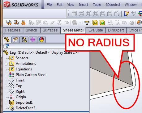
Upon review of our imported model, we discover that this cutting table project is entirely sheet metal. We will proceed to verify the thickness, bend radius, and flat layout data. I recommend using Gauge Table to define the standard sheet metal thicknesses, bend radius, and K-factor.
Figure 4a shows that the inside bend radius of our imported model for the leg is 0.125 in. (3.175 mm). The Convert to Sheet Metal tool will preserve that radius. If we want to change that radius—to match our tooling, for example—one solution is to use the Face>Delete tool with the Delete and Patch option set. Figure 4b shows the selections, and the result is shown in Figure 4c. Even though the outside radius is incorrect, we can now proceed to use the Convert to Sheet Metal tool.
We need to select a fixed face and an edge that represents a bend. We also specify the thickness and inside bend radius. You have the option of using Gauge Table to help goof-proof the data entry. Figure 5 shows the setup for this process.
The review process will help us to determine whether the design is suitable for stamping, CNC punching, or laser cutting. For example, kerf widths and minimum hole sizes may dictate laser cutting, whereas production quantity and unit cost may dictate stamping with progressive tooling. Cost considerations aside, this project’s features can be made with various metal cutting processes, such as stamping, punching, laser, waterjet, or plasma cutting.
During the review process, we also enter data for title block details to specify material alloy, material thickness, edge deburring, graining, plating, painting, screen printing, along with part numbers, revision, and intellectual property rights declarations. Figure 6 shows an example of the form in use.
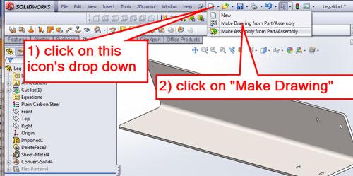
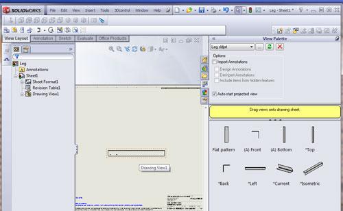
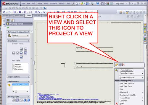
Now that we have a model that is properly tuned for manufacturing, we’re ready to create a 2-D drawing. With the part open, click on Make Drawing from Part/Assembly, as shown in Figure 7a. Then select a drawing template and click OK (see Figure 7b). The View Pallet appears on the right side of the screen. Just drag any of the starting views onto the drawing. In Figure 7c the “right” view has been dropped into the drawing as Drawing View1. Use the Projected View tool to add projected views as shown in Figure 7d.
As we create a 2-D drawing referencing the 3-D model, the software provides assistance in creating properly projected views—either allowing us to drag and project views manually or to insert multiple views automatically. The drawing template fills in the title block using data extracted from the 3-D model. All that remains is the addition of dimensions to complete the drawing. Figure 7e shows what a shop drawing might look like after a few minutes of work.
Next month we’ll continue our theme of speeding the manipulation of CAD models for the benefit of manufacturing. We still need to make a BOM drawing for this project!
Gerald would love to have you send him your comments and questions. You are not alone, and the problems you face often are shared by others. Share the grief, and perhaps we will all share in the joy of finding answers. Please send your questions and comments to dand@thefabricator.com.


The Fabricator is North America's leading magazine for the metal forming and fabricating industry. The magazine delivers the news, technical articles, and case histories that enable fabricators to do their jobs more efficiently. The Fabricator has served the industry since 1970.
start your free subscription
Easily access valuable industry resources now with full access to the digital edition of The Fabricator.

Easily access valuable industry resources now with full access to the digital edition of The Welder.

Easily access valuable industry resources now with full access to the digital edition of The Tube and Pipe Journal.

Easily access valuable industry resources now with full access to the digital edition of The Fabricator en Español.
In this episode of The Fabricator Podcast, Caleb Chamberlain, co-founder and CEO of OSH Cut, discusses his company’s...


