


Electrical Engineer
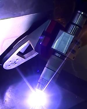
Figure 1: Recent developments in plasma cutting have resulted in new technology that makes up for some of the historical shortcomings associated with plasma beveling.
As any metal fabricator can tell you, a shop is only as efficient as all of its processes—not just one.
For example, if a fabricator uses a plasma cutting table of some sort and it slices right through metal but can't bevel, that shop has a problem. Believe it or not, that time spent beveling is eating away at profits, because today's plasma cutting equipment can bevel while the workpiece is on the table. Afterward, the material doesn't have to be moved to a prep area, and an operator doesn't have to spend several minutes getting the workpiece in shape for the welder. The fabrication is completed much more efficiently as a result.
That scenario isn't necessarily hypothetical. Many fabricators still rely on plasma cutting technology, but they are missing out on newfound efficiencies. To get an idea of just how far plasma beveling (see Figure 1) has come in recent years, let's take a look at some of the technological leaps that have occurred.
Most fabricators probably are familiar with the different bevel cuts (see Figure 2). Likewise, they are familiar with some of the historical shortcomings of plasma beveling. However, that was then, and this is now.
What was: In the past the degree of plasma taper angle was from 2 to 6 degrees.
What is: With today’s new high-definition/high-density power supplies, the standard degree of taper has been reduced to 0.5 to 2.5 degrees. That taper range depends on the power supply. Typically, taper angle for straight I-cuts can be produced consistently with no more than 2 degrees' positive taper angle under proper conditions.
What was: Height controls or arc voltage controllers were functional, but not precise.
What is: The distance from the workpiece to the material is precisely controlled. All torch height control (THC) parameters are fully embedded in the part programming, which allows for complete control of the cutting head and flexibility when change is needed.
Also, the set point for arc voltage control is achieved with a much higher response rate than with older stand-alone arc voltage controls. Arc voltage control used for beveling is now a function of the CNC, which monitors the arc voltage feedback—actual torch-to-work distance—and commands any correction in real time to achieve the set point commanded.
What was: Initial height sensing typically was done using some mechanical device. This assembly allowed the torch to move upward to contact the material, activating a switch. This in turn signaled back to the CNC that the plate had been detected. The distance that the torch moved upward to activate the switch was then subtracted from the retract distance to the piercing height. The piercing height, also referred to as ignition or transfer height by some manufacturers, is the height that torch ignition occurs at.
Some equipment utilized a mechanical device that required an offset position move to the torch position. Others incorporated this device directly on center using the actual torch holder.
What is: These devices were employed mainly an as alternative to plate detection using stall force detection or ohmic contact. Typical stall force detection monitors in real time when the torch has contacted the material and the motor is stalling or being prevented from moving at the commanded speed. This, therefore, causes a following error to build. Once this following error, or position error, exceeds a specified limit, the control assumes that the torch is on the plate, and motion is then halted and commanded in the opposite direction upward to the piercing height. This method typically doesn’t work because of the mass of the beveling heads and high gearing ratios of the Z, or lift, axis.
With today’s newer plasma torch designs, the ohmic sensing ability is integrated into the torch body itself—with the wire embedded within the torch lead set. In the past, to sense the plate using ohmic contact, an external wire was manually attached to the shield cap, but the plasma bevel process easily destroyed the wire during cutting. Now ohmic contact plate sensing occurs when the torch basically creates a short circuit to the work. Once this short is detected, the control knows that the torch shield cap is in contact with the plate.
Although ohmic contact is the best approach to achieve initial height sensing, a mechanical means, unfortunately, is still required in special circumstances such as a backup when cutting heavily scaled plate and epoxy-primed plate or when underwater cutting.
What was: Plasma cutting equipment used to have limited degree of taper, which prevented a short arc length to the material and hampered its ability to make 45-degree bevel angles. The arc voltage, as a result, had to be increased to produce these angles. This increased arc voltage, or torch-to-work distance, then increased the arc length, which extended the arc beyond its window to provide the best cut quality.
What is: Today plasma torch designs accommodate 45-degree tapered shield caps. With the newer torch and consumable designs, the arc length is greatly reduced, improving overall quality and feed rates.
What was: Programming software packages for a plasma beveling application used to be limited. The post files were limited to generating code for processing basic bevel segments. Plasma and THC process codes were not included within the part programs. Plasma beveling tables were basic, and program code was not optimally generated for multiple-pass bevel types. This caused hours and hours of real-time testing to create data to provide acceptable results using power supplies that had inconsistent degrees of taper angle.
What is: Beveling software has greatly improved because the beveling equipment-makers work directly with software providers. The programming software now has a huge impact on the plasma beveling process. A poor programming package will produce a poor overall result and create countless hours of lost production for the fabricator.
What is now available in terms of plasma beveling technology is much more user-friendly and efficient when compared to what was once commonplace. However, to understand just what the technology is capable of, further explanation is warranted.
Let's start with the power supply. The newest generation of high-definition/high-density plasma power supplies offer up to 400 amps using the oxygen plasma process to cut mild steel. These systems offer the best-quality cuts, higher cutting speed, and much reduced overall taper angle when compared to higher-amperage conventional plasma systems.
With a 400-amp system, a +/- 45-degree cut can be achieved in material up to 2 in. thick. This process is achieved at a slow cutting feed rate of 9 to 10 IPM and requires special piecing routines from the posting software. Typically, a 30-degree cut is more acceptable at 2-in. thickness for production.
A 260- to 275-amp system is capable of a 30-degree cut in 1.75 in., but that's at the technology's ceiling. For production, a 45-degree cut on 1.25-in. material is acceptable. Beveling material thicker than 2 in. requires a higher-amperage plasma system.
In some instances, multiple passes are needed to create a specific bevel. Once again, knowledge of plasma beveling technology can determine the final part quality.
For best quality, the amperage selected should be able to cut the maximum thickness at the specified angle. Additionally, the amperage should fall in the middle of the equipment manufacturer's specified range for that type of cutting application. If amperage is too high, excessive top- or land-edge definition will become rolled over. This rolled-over edge may or may not be acceptable.
To provide a machined appearance without a rolled-over edge, the operator typically cuts the bevel angle first, followed by the land cut. The land cut, being an I-cut, is not a typical I-cut in this case. Special processing information is required from the control so that the land cut segment has a smooth appearance.
A negative bevel cut is typically the most difficult to achieve, especially at a 45-degree angle. With a negative bevel angle, the scrap side of the cut face is actually kept, and the quality side is discarded when processing external cuts in a clockwise direction. Unique programming is required to process these negative bevels. Also, this bevel segment typically is processed first, before other passes, to achieve the best quality.
When the negative bevel cut is complete, the operator can see that the scrap side of the plasma cut usually has the more tapered angle. For this reason, when a negative angle on mild steel is programmed, the actual angle commanded is always more than the actual angle desired. The torch typically is required to be 2 to 3 degrees more for negative bevel segments.
The K-cut is the most difficult bevel to process and requires the most flexible programming software package to achieve a quality result. Typically, the negative bevel is processed first followed by the land cut. Finally, the positive bevel cut completes the segment. This approach produces the least amount of arc rollover and gives a machined appearance of the bevel face.
The advancements in power supply technology have been impressive, and modern CNCs have helped to pave the way for their use in shops. Today all plasma process and height control variables can be adjusted with a simple change in the program code.
Some work, however, still may be required. For example, program angle is a function of the software. The program angle commands the tilt axis to the specified angle. The actual angle achieved is influenced by many variables and is independent of the programmed angle. The program angle can be controlled easily and accuracy determined, but the actual angle is influenced mainly by beveling head alignment and plasma consumable condition. A simple test cut can reveal an actual result, which then can be entered into the software to create a "programmed" angle that is close to the actual angle. This test should be done only if the machine and torch meet the equipment manufacturer's operating specifications.
Software tool tables help as well. These beveling tables typically are embedded within the programming software package and allow the program file to be created in a single step. If the beveling attributes are applied at the CNC through an additional software program, this creates a two-step process that is typically undesirable.
The beveling tables are critical to process quality beveled parts, and data input must be entered and maintained properly. Poor data input contributes to poor results output. Bevel data collection for input within these spreadsheets is not a difficult process but can be time-consuming if done randomly, without first confirming machine accuracy, beveling head integrity, and plasma system performance.
The machine manufacturer should provide simple, straightforward procedures on how to establish beveling data for a particular material type and thickness. Beveling data development should be a major part of the machine training. Machine operators and programmers acquire vast knowledge of the plasma beveling process during this information-gathering.
The data collection for a particular material type and material thickness at a predetermined amperage can take some time during the learning phase. Once the concept is understood, however, data can be culled easily in a short period of time. Data generally can be gathered for angles using a 3- by 3-ft. plate and cutting in 5-degree increments starting from +/- 45 degrees. The whole cutting exercise should take three hours or less.
A bit more time is required on material thicker than 1 in. because of the material's size and the requirement that it cool after cutting. Many fabricators do not require all angles in 5-degree increments. The most common angles are 17.5, 22.5, 30, 37.5, and 45. The time needed to generate all process, THC, and kerf compensation data for these angles for a given material type, its thickness, and corresponding amperage level should not be too great once the plasma beveling process is understood.
Modern plasma cutting equipment can deliver bevels capable of streamlining welding and assembly activities down the production line. As with any piece of equipment, the operator plays a key role in making sure the machine can deliver as expected.

The Fabricator is North America's leading magazine for the metal forming and fabricating industry. The magazine delivers the news, technical articles, and case histories that enable fabricators to do their jobs more efficiently. The Fabricator has served the industry since 1970.
start your free subscription
Easily access valuable industry resources now with full access to the digital edition of The Fabricator.

Easily access valuable industry resources now with full access to the digital edition of The Welder.

Easily access valuable industry resources now with full access to the digital edition of The Tube and Pipe Journal.

Easily access valuable industry resources now with full access to the digital edition of The Fabricator en Español.
In this episode of The Fabricator Podcast, Caleb Chamberlain, co-founder and CEO of OSH Cut, discusses his company’s...


