


Senior Regional Sales Engineer

Figure 1: A filter’s nanofiber media coats the substrate. This prevents particles from loading into the depths of the filter and makes pulse cleaning effective to help extend filter life.
Plasma and laser cutting are bedrock processes of flexible metal fabrication. Nevertheless, they produce extremely fine particles that can present a variety of risks detrimental to machinery and employees.
Thermal cutting creates particulate that has to be filtered. Material removed during cutting produces slag; smoke; and fine, thermally generated particles. Slag typically drops to the bottom of the table floor, while smoke and fine particles rise above the workpiece unless adequate downward airflow—generated by the dust collection system—overcomes the thermal rise. Particles can range in size from submicron to dozens of microns, and controlling them requires a properly selected and installed filtration system.
System designs depend on the cutting environment and process parameters. A large plasma table has different airflow requirements than a small laser table. Plasma cutting produces different particle-size ranges than laser cutting. Even related functions, such as automated material loading, affect system designs because of increased cutting uptime. These factor into design requirements just as much as material type and thickness, cutting kerf widths, and part nesting.
In essence, a well-designed dust collection system should transform the entire cutting work envelope into an effective fume-capture system.
Getting dust collection right is essential for both environmental and operational reasons. In recent years OSHA has significantly lowered the permissible exposure limits of many dusts, including manganese as well as hexavalent chromium from cutting chromium-rich metals like stainless steel. The EPA continues to focus on not only the reduction of particulates 2.5 microns and smaller, but also other metal compounds including cadmium, chromium, lead, manganese, and nickel, all produced in a variety of metal fabrication and finishing operations.
Air used in controlling thermal cutting fume and contaminants can contain hot sparks. If sparks are not eliminated, they can be conveyed to potential fuel throughout the dust collection system. Controlling ignition sources is therefore critical to avoid the damage and disruption fires create. Also, if filtered air is returned to the production area, secondary filters can confirm the operational performance of primary filters, ensuring the returned air is clean and safe.
Shops also must consider risks from capturing particulate of different materials when they may be incompatible. For example, this could include particulate from dissimilar metals, where the metals and metal oxides may represent the potential for a thermite reaction. Combustion risks affect filter system layouts and design decisions. The National Fire Protection Association (NFPA) publishes several standards that can be applied to help mitigate the many risks associated with combustible metal dusts.
Effective dust collection starts with hoods that efficiently capture and control particulates. System performance is limited to what the hood can accomplish. Buying the most expensive dust collector and installing high-efficiency filters will not increase overall efficiency beyond 50 percent if the hood captures only half the dust and fume.
In thermal cutting, the cutting table is the capture hood. The hood must pull consistent air volumes continuously to capture contaminants. If it doesn’t, dust and fume escape.
Fiber area, not filter area, is a key to effective filtration. The filter design should therefore include lots of small fibers to increase the available fiber surface area by orders of magnitude.
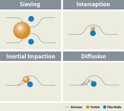
Particles interact with filter media in various ways. Typical filtration explanations focus on sieving, but more advanced models account for the benefits of materials like nanofibers, which allow filters to collect smaller particles using interception, inertial impaction, and diffusion.
Basic traditional filter media enhanced with a layer of nanofibers will provide high filtration performance in capturing fine particles from thermal cutting. This layer of nanofibers increases the filter media’s efficiency dramatically when working with thermally generated particles. Nanofibers also prevent fine particles from embedding deep within the filter fibers, forcing particles to accumulate at the media’s surface (see Figure 1). This creates an extremely effective surface-loading filter.
Surface loading shows its benefits with pulse cleaning of the filter. Most pulse-cleaned dust collectors incorporate a compressed-air manifold and diaphragm valve arrangement. When a pilot solenoid valve is energized, the diaphragm valve allows compressed air to exit the manifold as a “pulse,” which forces particles off the filter surface. Effective pulse cleaning drives the dust off the filter media and into a storage container.
Surface-loading filters stop the particles at the surface of the media where it is easily pulsed off, extending filter life and reducing energy consumption (see Figure 2). If particles are not stopped on the surface, filters depth-load, which allows fumes to enter the depth of the media. It is very difficult if not impossible for pulse cleaning to discharge these depth-loaded particles. This in turn shortens filter life and increases energy consumption.
Dust Load
The amount of dust produced by an application, or its dust load, influences the size of the collector needed, as a high dust load increases a dust collector’s work load. Over a given time period, laser cutting may produce less dust than plasma cutting. Although the airflow needed to capture the fume from laser cutting and plasma cutting may be identical, dust collector sizes might differ because of the different dust loads.
Lower dust loading from laser cutting might suggest less collector work load, but particle size also plays a role. Smaller dust particles on the filter tend to cake together, with smaller void spaces between particles, which in turn increases the pressure needed to pull air through the layer of dust. If this isn’t accounted for, a dust collector may consume more energy and require more frequent cleaning.
Heat Load
All dust collection systems have temperature limits and any increased heat load may require different system construction. Under some circumstances cooler air may need to be bled into the system to keep the total air temperature within the collector’s operating limits.
Heat load and hood design also differ among processes. Oxyfuel cutting, for instance, generates relatively low dust loads but produces significant heat. This additional heat load must be accounted for when selecting the dust collector’s materials of construction—especially the filters. Plasma cutting and laser cutting generally generate a lower heat load but produce heavier dust loads.
Table design can also affect heat load. For instance, structural cutting lines may use a plasma torch to cut beams or plates, with sparks and melted metal evacuating through a narrow slot below the cutting zone. This will generate higher heat loads than traditional open-area downdraft cutting tables.
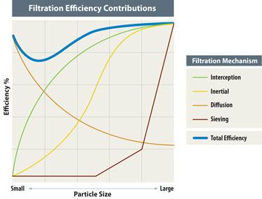
Different filtration mechanisms have different levels of efficiency, depending on the particle size being filtered.
Automation also changes collector sizing considerations. In manual cutting, operators take parts off of a table and then load new sheets. During this downtime a dust collector can “catch up” on pulsecleaning under heavy load conditions.
Automated material handling switches out finished sheets in minutes, so cutting and part removal occur at the same time. This feature increases shop productivity, but it makes dust collection more challenging, because the collector is exposed to more cutting time and has less time to “catch its breath.” Such automation often leads to higher dust and fume loads, and a dust collector should be sized to accommodate those loads.
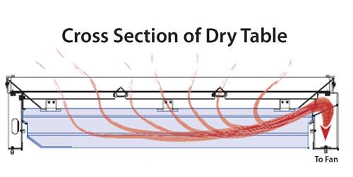
To effectively capture fume and dust from a cutting process, a fan draws air past the workpiece downward through the cutting table to create an airflow pattern (see Figure 3). The fan provides the energy to overcome turbulence and friction losses as air moves from the cutting zone, through the ducts, the collector, the filter media, and through the dust cake.
A properly designed dust collection system should pull the required air volume (cubic feet per minute, or CFM) constantly. Too much air will shorten filter life, and too little air will reduce the system’s capture efficiency. The energy required to overcome the resistance in the system, or the static pressure, changes over time as filters become dirty.
Static pressure values often are expressed in inches of water gauge, which are mere fractions of a pound per square inch—about 27.7 inches of water equals approximately 1 PSIG. A new, clean filter starts with very little airflow resistance, often less than 1 inch, but over time the dust accumulation on the filters increases resistance to several inches. Filters should be replaced as resistance begins to exceed a certain point. In many cases, this may be 5 or 6 inches, but in some instances filters aren’t considered plugged until their resistance reaches much higher levels.
To extend the operational life of the filter media, a modern dust collector uses pulse-clean filters. This periodic reconditioning allows these systems to run continuously without frequent filter replacement.
Under normal operation, a dust collector achieves a stable, “seasoned” condition where the filters have a relatively uniform resistance a few inches higher than when new, because of the filter cake that forms on the media surface. Over time some degree of depth loading and other actions will gradually plug the media, increasing resistance slowly. Eventually it will prove more cost-effective to replace the filters than to attempt continued operation at higher fan energies.
To ensure effective performance throughout the life of the filters, fans generally are sized to deliver the desired air volume at the “plugged” pressure drop of the filters—that is, the highest, or “terminal,” pressure-drop condition.
To ensure the optimum operational life of the filters, a dust collector must have a controlled air volume to avoid pulling excess air through the system. Dust collection systems therefore often incorporate a damper on the fan to adjust for resistance changes in the filters as they become plugged. The partial closure of the damper ensures the fan pulls only the desired air volume when the filters have relatively little resistance. Dampers, however, are not the only way to control airflow; adjustable-speed motors allow fan speed and, therefore, performance to be adjusted to not only control airflow, but also to allow energy savings.
The greater the air volume required to control the dust and fume from cutting, the larger the dust collection system. Consequently, many large cutting systems will be compartmentalized, or “zoned.” This approach requires airflow only in the space below the cutting bed, translating to a smaller air volume and thus a smaller dust collection system.
In other situations, the stock being cut may have existing openings that create the need to pull additional air, and dust collectors should be designed with this extra capacity requirement in mind. Increasing the collector capacity in this instance ensures the system maintains the necessary downdraft velocity across all the openings for effective dust evacuation.
Finally, a collector fan should generate sufficient airflow through the cutting table to create the downdraft velocities needed to capture rising fume. Air velocity typically needs to reach 150 to 250 CFM to control fume effectively, but this requirement may increase depending on the table design, size, and cutting process.
Many variables influence dust control system performance during thermal cutting, and a well-designed system including the ducts, fan, and filtration media should take all the variables and elements into account. When well designed, the system should maintain consistent downward airflow velocity to effectively evacuate dust across a range of filter and operational cutting conditions.
The bottom line: Designing and integrating an effective dust collection system for thermal cutting is not a one-size-fits-all exercise. Balancing all the factors will help a shop ensure it gets the most out of it.
To understand dust collection systems, it helps to know how particulates interact with filter media—that is, the filtration mechanisms. The most commonly understood is sieving, where filter fibers block particulate from passing through because openings in the filter media are smaller than the particles. But this is not the only mechanism that filters particles from an airstream. In fact, sieving plays a relatively small role in capturing the very fine particles generated in laser and plasma cutting.
When dust particles make physical contact with a fiber’s surface in the filter’s structure, they stick, and it is this principle that allows filters to capture much of the particulate produced by thermal cutting.
Inertial impaction is the filtration mechanism commonly at work when large, heavy particles begin to follow the airstream around a fiber, but because they have too much mass to make the turn, they impact the fiber. For illustration purposes, consider air passing over a car windshield in a snowstorm. Smaller, lighter snowflakes follow the airstream and pass over the car windshield without making contact. Heavier, wet snowflakes fail to make the changes in direction and hit the windshield.
Interception is the mechanism at work when the outer diameter of a particle is just large enough that it will graze the fiber surface as it attempts to pass. That brief touch represents enough contact with the fiber surface to cause the particle to adhere.
The final filtration mechanism is diffusion. This is the primary filtration mechanism affecting submicron particles. These particles are so small that individual air molecules around them influence how they move within the general airflow. The particles are bounced around within the airstream, moving every which way. Consider trying to get to your seat at a sports stadium during a break in the action. You may be moving with the general flow, but if you are really small, you get bumped and jostled as you move toward your seat. Your path is not very straight, and if you happen to be near the edge of the crowd, you bump into rails or a wall at some point. Those patrons are like air molecules jostling a small particle until it strikes a surface.


The Fabricator is North America's leading magazine for the metal forming and fabricating industry. The magazine delivers the news, technical articles, and case histories that enable fabricators to do their jobs more efficiently. The Fabricator has served the industry since 1970.
start your free subscription
Easily access valuable industry resources now with full access to the digital edition of The Fabricator.

Easily access valuable industry resources now with full access to the digital edition of The Welder.

Easily access valuable industry resources now with full access to the digital edition of The Tube and Pipe Journal.

Easily access valuable industry resources now with full access to the digital edition of The Fabricator en Español.
In this episode of The Fabricator Podcast, Caleb Chamberlain, co-founder and CEO of OSH Cut, discusses his company’s...


