


Contributing Writer
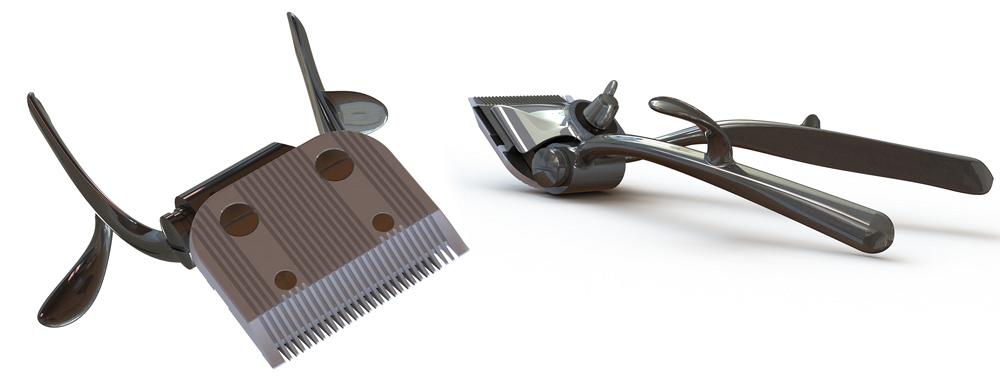
Figure 1
On the left is a view of the soleplate of a pair of manually operated hair clippers. From the top side, the wing nut adjusts the tension between the blades, and the spring cap sets the pressure between
the handles. (image on the right)
Editor's Note: If you would like to see a video of the 3-D CAD model, click here. If you would like to download the 3-D CAD files, click here.
The hair clippers shown in Figures 1a and 1b are of an antique design—patented in the late 1890s. In 1901 Brown & Sharpe manufactured hair clippers like these in Providence, R.I.
The 3-D CAD model is my attempt at cloning an actual pair of clippers that date back to at least 1930. I encourage you to download and examine it.
The reasons to admire this manually operated design are many. As evidence of merit, they still cut hair very well after more than 80 years. They fit in the hand and balance nicely. They are easy to clean and robust as well. The master craftsmen behind this product have a lot to share.
Fabrication processes—including precision grinding of hardened steel—drove several decisions related to this original product design. Form follows function throughout.
Incredibly, these were designed and manufactured without the aid of 3-D CAD! The swoopy parts were probably modeled with wood or clay. That pattern was then used to create the molds for casting.
3-D CAD offers two advantages over hand-carved master patterns. First, the 3-D CAD model allows for dimensional accuracy and efficient editing as needed to refine the model. Second, the CAD model does not wear out and can be used to make an infinite number of identical billets for manufacturing.
The 3-D CAD software used in support of this article can be described as history-based and parametric. (Direct modeling is a term used in competing CAD technology that attempts to simplify the production of swoopy shapes.) Our hair clippers present a variety of modeling challenges: patterns of slots, curved shapes, the need for manufacturing documentation, and kinematic motion of parts. The mainstream 3-D CAD software used in support of this article is designed to accomplish all of those goals.
For the easy-to-mill parts, the 3-D CAD solid modeling is convenient. As a CAD technique, solid modeling involves sketching a profile, extruding that 2-D profile into 3-D space, and then cutting away any extra stuff.
Surface modeling is an alternative to solid modeling techniques. Surface features have fewer “helping hands” behind the scenes and can be a more versatile technique when it comes to modeling swoopy shapes. Hybrid modeling describes a combination of solid and surface modeling techniques. A rationale in selecting one technique over the other will be considered as we tour through the components in the hair clipper mechanism.
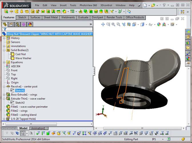
Figure 2
The two pieces in the wing nut assembly are modeled as a pair of bodies in a multibody part.
Figure 2 is a screen shot of the wing nut model. This part will be manufactured in three stages:
For speed in modeling, a multibody CAD technique works well. Both the nut and the wave washer reside in the same CAD file. Multibody allows convenient assignment of material and appearance. Solid modeling techniques were used, again, because of convenience and suitable representation of the finished part.
The modeling approach is to revolve the main body, extrude the wings, extrude the wave washer, add fillets for shape refinement, and tap the through-hole.
The history of modeling steps is shown in the Feature Manager, which is the left side of the screen in Figure 2. For clarity, the two solid bodies shown near the top of the Feature Tree were renamed to “Cast Nut” and “Wave Washer.” This better documents the intent of the model’s features. We offer this renaming of features as an example of a good CAD habit.
Figures 3a and 3b show the top and bottom of the blade cover. As the wing nut is tightened, this cover applies pressure against the upper blade to set the tension of action.
The modeling history reveals that this is a hybrid model; it uses both surface and solid modeling features. We might be tempted to use a shell feature instead of knitted surfaces. However, this part does not have uniform wall thickness. Boundary-Surface1 is the outer surface, and Boundary-Surface2 is the inner surface. Their independent controls allow for fine-tuning of the wall thickness for optimal material flow during casting.
The overall modeling approach was to define planes to control the location of mounting surfaces. Then 3-D sketches were drawn, sometimes using planes for constraint and other times using conventional dimensions in the sketch. Those sketches represent the perimeter of the desired surfaces. All surfaces of the casting were modeled, trimmed, and then knitted to form a solid.
The convenience of the Hole Wizard for cutting the counterbore and the Sketched-Text Cut-Extrude for the part marking make the surface knitting operation for solid modeling a real time saver for the CAD jockey.
Figure 4a shows the bottom side of the upper blade. The actual manufacturing process this model represents called for forging the blade body, stamping the forging to fine-blank the guide slots and lever engagement, hardening and tempering the blank, and grinding to create the final slide bearing surfaces and teeth.
This component was modeled using solid modeling techniques simply because of the convenience of the available tools. A couple of time-saving techniques—a Cut-Sweep for the tooth grind and a Pattern Feature to create the other 25 teeth—should be noted in Figure 4b. A pair of planes allow precise control over where the tool grind path is located as well as its angle relative to the part. The Cut-Sweep in this example arbitrarily follows a straight path; it could have been modeled just as easily with a simple Cut-Extrude.
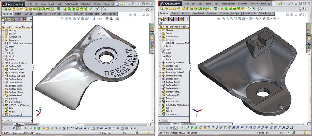
Figure 3
Left image shows the top side of the cast aluminum tensioner cover is polished for good appearance. The part marking is stamped post-casting.
Right image shows the interior of the cover is as-cast. The nonuniform wall thickness was modeled using surface features that were later trimmed and knitted together to form a solid body.
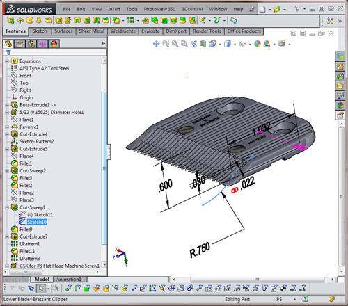
The bright blue line in Figure 5 shows the more complex grind path in the lower blade. Here, the grinding wheel follows two arcs to create a slot between teeth. A pattern of this feature creates the 25 teeth.
The pattern of grooves in the floor of the blade takes advantage of the ability to skip instances in the pattern. That’s how the flat zone for the countersinks and post swages were created.
The perimeter of the lower blade has a hand-polished finish. This was modeled with a Cut-Sweep, and the result is generally similar to the as-fabricated product.
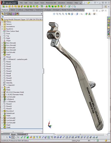
Figure 6a shows the rather lengthy feature history for the solid model of the swinging handle. The handle’s pivot hole and blade engagement hook are easy to represent with solid extrudes and cuts. The swoopy shape of the handle is best modeled with knitted surfaces to achieve convenient editing. (That demonstration is a topic for a future article in this hair clipping serial. We will persevere with an exclusively solid model for the swinging handle for future comparison with surface modeling techniques.)
A solid Loft feature was used to model the handle shown in Figure 6a. To control the loft’s shape, the CAD jockey creates a 3-D sketch that represents the centerline along the handle’s casting. A style-spline was used in that 3-D sketch to define the centerline path of the handle. Style-splines are very easy to manipulate with the mouse. The CAD jockey also can add dimensions to precisely control the shape of the resulting 3-D spline.
Sketch points along that 3-D spline were used to define planes. Sketches on those planes represent cross-sections through the handle’s casting. We ended up with less than a dozen profile sketches in this Loft. In addition to these profiles, a set of 3-D guide curves were drawn—similar to the centerline 3-D sketch—to control the Loft’s connection between the profiles.
The resulting model is visually similar to the actual part. However, the solid Loft feature represents some very sophisticated underlying math to represent transitions from profile to profile. The consequence is a model that is very sensitive to small changes in the location of sketched profiles. For the purposes of this model, the results are acceptable. (As foreshadowing, the closed loops in the 2-D sketched cross-sections get replaced in a surface modeling technique; instead of closed loops, open segments represent edges of surfaces.)
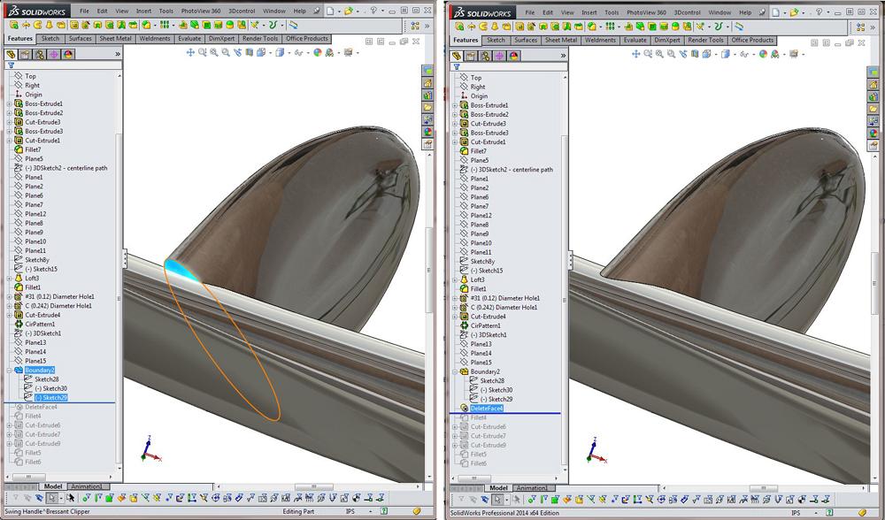
The finger rest was modeled as a solid Boundary feature. The unfortunate result is shown in Figure 6b. The flat face is an unwanted artifact. Figure 6c shows a solution provided by Delete Face, a wonderful tool for blending things together.
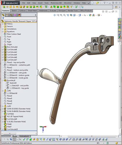
The stationary handle model shown in Figure 7 differs from the handle in Figure 6a in an important way: This handle does not have the long flat zone that the swinging handle has. We might get away with fewer sketched cross-section profiles.
The model in Figure 7 uses a solid Boundary feature instead of a Loft. Boundary features are designed for control, whereas Lofts are convenient for relatively simple shapes.
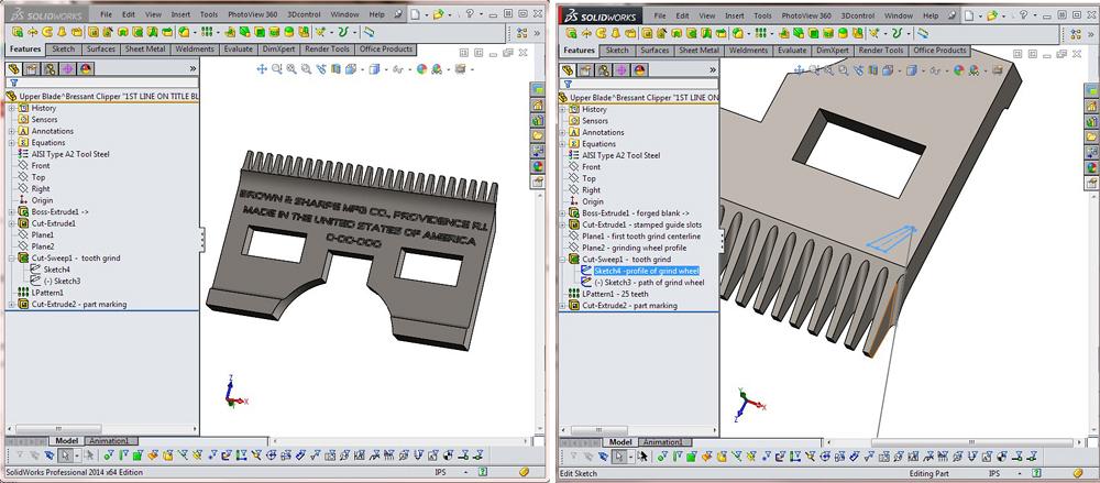
Figure 4
On the left: This blade is forged steel, hardened and ground. Solid modeling features such as Cut-Sweeps and linear patterns are convenient and accurate for modeling this part.
On the right: The teeth are modeled in a manner similar to as-manufactured. Grind a groove between the teeth and repeat for the sides of all 25 teeth. The result of grinding was modeled by using a Cut-Sweep.
In this example, the controls we create for ourselves are end profile sketches—one at each end of the handle’s surface. A 3-D sketch is drawn as a guide curve to shape the boundary connection between the profile sketches. This resulted in efficient editing of the handle shape.
As a refinement, a Loft was used at the end of the handle to create the finished round end. The visible line is a result of surfaces that are in contact but not in continuity. Removing that line is another candidate for hybrid modeling.
Gerald would love to have you send him your comments and questions. You are not alone, and the problems you face often are shared by others. Share the grief, and perhaps we will all share in the joy of finding answers. Please send your questions and comments to dand@thefabricator.com.


The Fabricator is North America's leading magazine for the metal forming and fabricating industry. The magazine delivers the news, technical articles, and case histories that enable fabricators to do their jobs more efficiently. The Fabricator has served the industry since 1970.
start your free subscription
Easily access valuable industry resources now with full access to the digital edition of The Fabricator.

Easily access valuable industry resources now with full access to the digital edition of The Welder.

Easily access valuable industry resources now with full access to the digital edition of The Tube and Pipe Journal.

Easily access valuable industry resources now with full access to the digital edition of The Fabricator en Español.
In this episode of The Fabricator Podcast, Caleb Chamberlain, co-founder and CEO of OSH Cut, discusses his company’s...


