Contributing editor
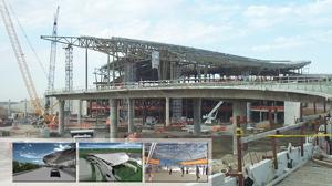
Some events alter the course of everything that occurs after. The new Indianapolis International Airport terminal is one of the first airport buildings to be designed, fabricated, and built to survive the type of attack inflicted on the World Trade Center on Sept. 11, 2001.
The building's "blast" design is engineered to prevent the roof from collapsing upon impact from a Sept. 11-type blast, according to Brian Wessel, project manager for Cives Steel Co., the project's primary steel contractor. If members or columns were to be damaged, the roof structure is designed so that the loads would be dispersed throughout the other columns and portions of the building and roof, Wessel said.
In addition, the new airport—a $1 billion project—is intended to be an air-travel gateway for "The Crossroads of America"—a modern, clearly identifiable landmark, according to the Indianapolis Airport Authority. In total, 8,000 tons of steel will steel the terminal and two concourses.
The heart of the new terminal will be a circular space—a civic plaza dominated by its great, arched roof, the Authority says. The roof's curvilinear design is intended to be a canopy for socialization, public events, artwork, recreational dining, and a travel destination, as well as to be energy-conserving and environmentally considerate.
The civic plaza design includes architecturally exposed structural steel (AESS)—a departure from the traditional approach—so most of the fabricated members will be viewable by millions of air travelers.
Fabricating the serpentine structural trusses, specialty barrel joists, and tapered-pipe columns of the rolling, snakehead roof to help materialize these ambitious aspirations was the mission of Canam Steel Corp. and Hillsdale Fabricators, St. Louis, for Cives Steel, Roswell, Ga., the primary steel contractor.
"Because it is a serpentine roof—it's actually sloping and curved in two directions—we had to deal with a lot of complex geometry," said Wessel (seeFigure 1).
An extensive "flight plan" had to be executed to ensure that the fabrication of 2,500 tons of steel was done correctly and so that it was delivered by the ETA in the sequence it was needed to be erected at the job site. "We had to have a pretty substantial backlog of roof member fabrications to facilitate the erection operations without impacting the job's overall progress schedule," Wessel said. "Months of planning, coordination, and meetings back and forth went into this before our detailer put pencil to paper."
The roof trusses, which run both north/south and east/west, were rolled at a 1,260-ft. radius to create the slope. "So it's a fairly gentle roll, but over the length of the building, the curve is quite substantial," Wessel said.
The trusses are 10 ft. deep with a wide-flange top chord 6G welded to diagonal and vertical pipe that is welded to a 16-in.-dia. pipe bottom chord, Wessel said (see Figure 2).
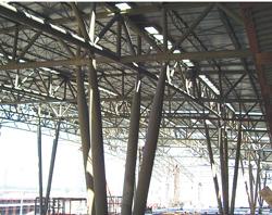
Figure 1The serpentine roof slopes and curves in two directions, demanding complex geometry in the fabrication of the 2,500 tons of steel.
One of the biggest fabrication challenges was cutting the complex helical edges on the pipes used in the trusses because of the way the pipes fit onto other pipes, said Greg Peterson, director of business development, Hillsdale Fabricators (seeFigure 3). "If you can imagine, you have two or three pipes coming in vertically or diagonally to a single point on one horizontal pipe, and they all have to fit together." Too, to get a 6G, full-penetration, all-position weld, the pipe ends had to have good, accurate bevels cut, he said.
"You can't have large gaps and get a good connection. But this project had, literally, an infinite number of connection types and complex geometries and sharp angles coming at the working point," Peterson said.
Previously the company's fabricators had been executing these "fishmouth" cuts by wrapping a cardboard template around the pipe to guide the manual oxyfuel or plasma cutting. Then they had to do a second pass to cut a bevel, Peterson said.
After doing research, Hillsdale purchased a Watts Specialties Inc. automated, CNC, 24-in.-dia. pipe cutter. An operator downloads the detailing model to the machine control and it cuts each pipe to length, cuts curves, and bevels the edges simultaneously, Peterson said.
The maximum wall thickness the CNC machine can cut with a clean bevel that is weld-ready is about 3⁄4 in. thick, Peterson said. "At 11⁄2, 2 inches thick, you still have to come back and grind the bevel smooth."
Certifying enough of the company's welders to perform 6G all-position welding was a challenge, Peterson said. "It's just an extremely difficult process. If you can imagine welding underhand, overhand, and sideways...these are multiple-pass welds."
The trusses had to be shop-assembled while also having a field splice connection so that they could be constructible on-site, Wessel said (see Figure 4).
"Typically when you're splicing pipe for bottom chords, you just butt them end to end. We actually ended up using a stairstep-type splice," Wessel said. "We had to have a way for the erectors to set one section of pipe almost on top of the other to provide some stability during erection so that they could be bolted up in the field temporarily until the final welds could be done."
Canam fabricated the 400 barrel joists with canted seats and deck-bearing plates to follow the changing slope of the trusses. "The barrels were easy to run down the line, but to keep production flowing smoothly, we stacked them and returned them to the line for the application of the deck plate and rods," said Carl Brendel, longspan production supervisor of the Washington, Mo., plant where the fabrication was performed. The production shop beveled the seat plates piece by piece to achieve the minute changes in each of the details sent by the engineering team.
Additionally, the company fabricated 7,405 ft. of rods varying in size from 1⁄4 to 3⁄4 in. to support 1⁄4- to 1⁄2-in.-thick deck plate, 6 to 7 in. long.
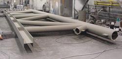
Figure 2The 10-ft.-deep trusses are constructed of a wide-flange top chord 6G welded to diagonal and vertical pipe that is welded to a 16-in.-dia. pipe bottom chord.
Some of the more unusual fabrications are tapered pipe, "torpedo" columns that support the trusses (seeFigure 5). These tapered-pipe columns were designed to take more of the load, Wessel said.
A cluster of four torpedo columns are pinned to the roof trusses to support them in both north/south and east/west directions, and then come down to a center node at the third-floor level below where they are connected to a cross-plate assembly, Wessel said.
Hillsdale fabricated the torpedo columns from standard, 30- to 40-ft.-long, 24-in.-dia. pipe to which the company welded 8 ft. long conical sections at both ends.
"There were 92 of those columns, so we fabricated 184 conical sections. They tapered from 24 inches in diameter at one end to 13 inches in diameter at the narrow end," Peterson said. The cones started as two trapezoidal blanks burned out of 11⁄2-inch-thick plate. Then the blanks were rolled into two half-conical sections, spliced and welded together with thick end plate connections, and beveled at the larger ends before being welded to the straight pipes, Peterson said.
"You've got a couple of issues. You have to [press] brake these continuously with the same force each time at 1⁄4- to 1⁄2-inch increments to form the cone, and at one end you're braking a lot more than at the other, wide end of the taper. Then you have to go back and bevel one edge to get complete weld penetration," Peterson said.
The rolling was an especially tricky situation, because the columns are all AESS. All of the roof structure columns will be exposed in the final airport construction, so waves, ripples, and sharp bends could not be visible.
"We had half the tolerance allowed for imperfections than if they were not AESS," Peterson said. "So now you have an extremely complex member and your allowable errors are decreased by half."
After the welds were inspected and tested, Hillsdale applied an epoxy putty to give the surface a smooth final appearance.
The base plate assemblies that the torpedo columns are framed into were constructed of a thick, 4-in. base plate with thinner plates vertical-welded in an X, or cross pattern, Peterson explained. "Those assemblies had to be full-penetration-welded, and the tops of those were all AESS. Then a single 4-in.-dia. pin connects the tapered columns to the base plate assemblies. The cross assemblies then sit on top of the third-floor columns to frame them to the main floor structure below," he said.
A zinc primer was shop-applied to the truss and column components. The final two coats of paint will be applied in the field once the trusses are assembled.
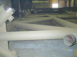
Figure 4The trusses had to be shop-assembled while also having a field stairstep-type splice connection so that they could be constructible on-site temporarily until the final welds could be done.
Many of the 198 trusses were 115 ft. long, so transporting them 245 miles by truck required trailers more than double the legal length load, Peterson said. "Twenty or 30 permit loads were needed—115 feet of steel, plus a long tractor, two escorts … it was quite a spectacle.
"In relationship to the fabrication, the erection took very little time, so we had to be ahead three or four sequences to make sure that we never shut the job down," Peterson said. "We were very successful. We never delayed the project because we couldn't deliver."
Once the field welds were done on the trusses, the torpedo columns were brought into position, and the final plate assemblies were final-welded. The pins were installed, and the shoring towers were jacked down to allow the roof structure to settle into its final position, Wessel said.
"Once the trusses were set and the columns were fixed, there's absolutely zero tolerance. It's basically just one giant weldment," Peterson said.
Cives, Hillsdale, and Canam just wrapped up their part of the project. "The last box girder was put in place Friday, July 27," Wessel said.
"Quality assurance was the most difficult aspect," Peterson said. "You're fabricating something that's going to be seen by millions of people a year. Few eyes can see imperfections, but those eyes that will … you want it to look right."
Although the airport project is not the largest Hillsdale has done—the company supplied structural members for the St. Louis Cardinals stadium and is currently working on the Indiana Colts stadium—Peterson said this one was significant.
"This was certainly the most difficult and most visually exposed project we've ever done. We take a great deal of pride in that project."
The airport's new main passenger terminal building is scheduled to open in September 2008.
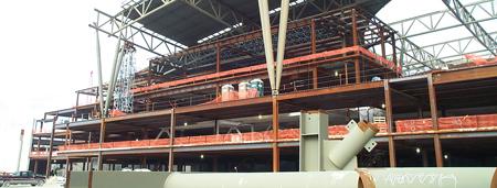
Figure 5Some of the more unusual fabrications are 92 tapered pipe, 'torpedo' columns that support the trusses, fabricated from standard, 30- to 40-ft.-long, 24-in.-dia. pipe to which the company welded 8-ft.-long conical sections at both ends.

The Fabricator is North America's leading magazine for the metal forming and fabricating industry. The magazine delivers the news, technical articles, and case histories that enable fabricators to do their jobs more efficiently. The Fabricator has served the industry since 1970.
start your free subscription
Easily access valuable industry resources now with full access to the digital edition of The Fabricator.

Easily access valuable industry resources now with full access to the digital edition of The Welder.

Easily access valuable industry resources now with full access to the digital edition of The Tube and Pipe Journal.

Easily access valuable industry resources now with full access to the digital edition of The Fabricator en Español.
In this episode of The Fabricator Podcast, Caleb Chamberlain, co-founder and CEO of OSH Cut, discusses his company’s...