


A trek in product design change and laser cutting
How a manufacturer takes its bicycles from concept to customer
 |
In Wisconsin farm country, not far from Madison, is the Waterloo headquarters and frame manufacturing plant for TREK bikes. Its 1,000 employees produce about 600 frames a day—300 metal (aluminum, titanium, or steel) and nearly that in carbon fiber. The frames then are sent to another plant for assembly into a bicycle.
Last year TREK designed and produced 13 new metal models, with an average of seven different sizes of each. The company replaces each model with a new one about every two years, and customers have come to expect that product life. Given that kind of turnaround, TREK manufacturing engineers face at least two challenges:
- Keep up with design changes
- Keep up with volume while ensuring a high-quality fabrication and finish
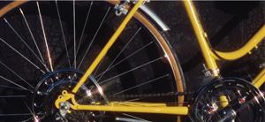
Some of the frame designs are like no other. Design teams at the plant create frames that minimize wind resistance, provide proper rigidity, and present an attractive appearance.
Changing Strategies for Changing Products
"When I first started here, we had round, oval, and a few arrow-shaped tubes," said Dean Garner, TREK manufacturing engineer, weld/frame build.
At the time engineers wrote laser code for round tubes using old spreadsheet software. For oval tubes, they scanned in the profile with a coordinate measuring machine and calculated laser cuts with a spreadsheet.
"Our previous CAM software would not handle sloped surfaces, which we were seeing more of in the frame designs. It could not help us cut a four-dimensional spline—X, Y, Z, and rotation—in our laser," he said.
 |
| TREK engineers use computer-aided manufacturing software to program a four-axis laser to cut the complex shapes found on this frame tube. |
Today TREK engineers use Power MILL software from Delcam Inc., Windsor, Ont., Canada, to program four-axis laser cutting of bicycle frame tubes. The software has a range of cutting strategies, including five-axis cutting techniques, as well as fast calculation times and helpful editing tools.
In light of today's changing surface shapes, "without a five-axis program, we would be writing the laser code one line at a time, which would take about a day per tube compared to about 10 minutes with [the software]," he explained.
Rotation and Tool Paths
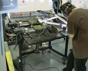
All aluminum, steel, and titanium frames manufactured in the Waterloo facility cross the laser tube cutting machine. The challenge for manufacturing is to keep the beam perpendicular to the part surface or it will be deflected to other parts of the room, which is dangerous as well as ineffective.
Z positioning of the laser is automatic to ensure correct focus, but "calculating X, Y, and rotation to prevent deflection of the laser is extremely important so that the laser follows the contour of the part," Garner said. "If you are off just a little bit, working with three-dimensional space, you could ruin the spline, and the material is costly. [The software] made it possible to cut the shaped spline to fit the joining piece with no gaps."
The operator chooses the application, the part number of the frame, the size and version, number of points around the tube, how to cut the part, and other details. The software generates the tool path around the part without further input from the operator. It also calculates the transition point between the inner spline and the outer spline, allowing the company to manufacture a smooth interface between frame components.
Most of the tool path calculations that used to be done manually now can be accomplished automatically by the software.
"All we have to do is set up the frame model in our desktop computer so [the software] can find the ends of the spline tube and generate a tool path for the laser," Garner said.
Each frame size may involve up to 15 different laser programs, and each frame set can have three to 15 sizes. The software creates all that and also breaks the tool path into pieces, so a section can be modified or deleted as needed to optimize the program and prevent having to run and revise the whole code.
"Once the tool paths are created, we can post that code to a program for a laser. Once posted, it shows how the laser will respond to what we have just done. If we like it, we can run that chunk of code," Garner said.
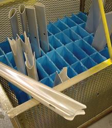
 |
| Before TREK installed its newest CAM software, the older software could leave gaps of 1 mm or more between bike frame parts. Now welders rarely see a gap greater than 0.1 mm. |
The automated postprocessor added by Delcam VAR Programming Plus Inc., New Berlin, Wis., reduces programming time from 30 minutes for some frame tubes to about 10 minutes.
Faster Time to Market
Although TREK has been laser cutting tubes for 10 years, the new software has allowed quick production of new, aerodynamic shapes. Production on a particular type of bike might be only a couple thousand in nine different sizes.
Under this scenario, tooling up to mill the details in each size would be cost-prohibitive. In addition, when the company is proving out a bike concept in the validation stage, geometry, dimensions, and other specifications might change after a few test rides.
Now engineers can go back and reprogram the laser code, sometimes having four or five iterations before being ready for production. Holding tighter tolerances with the software also has reduced the number of iterations, resulting in faster time to market.
Quality Fit
Today Garner's team programs the laser to chase some very tight corners on the new complex tube cross sections—impossible to program in a reasonable time frame without the software.
With the software, "we are getting a much tighter fit, piece to piece, and minimal gaps, if any, which means we can hold our overall frame geometry much better. Parts normally shrink as we weld them, and with a gap, shrinkage is much more uneven or random," Garner added.
Using previous CAM techniques, gaps between parts before welding could have been 1 millimeter or more. Today it is rare to see a gap greater than 0.1 mm, Garner said. The closer tolerance means a better fit-up, which makes it easier and less time-consuming to put the frame together.
After the aluminum tubes are cut on the laser, they are held in a programmable fixture for the first stage of welding. From welding, the frames are solution heat-treated to a soft state and aligned. After heat treatment, the frames are aged to their optimum temper and sent to machining. In machining, the bottom brackets are threaded, and the head tubes and seat tubes are reamed.
With the better fit and a more predictable frame, the bicycles can precisely match customer expectations. For instance, when a head tube is welded onto a frame, any gap will affect the location of the tire, which affects the ride. Closer tires provide a more competitive ride.
With the consistency of the laser cutting program, TREK can meet the design intent—downhill, touring, racing—for each different bike.
Trek Bicycle Corp., 801 W. Madison St., Waterloo, WI 53594, 920-478-9960, www.trekbikes.com
About the Publication
subscribe now

The Fabricator is North America's leading magazine for the metal forming and fabricating industry. The magazine delivers the news, technical articles, and case histories that enable fabricators to do their jobs more efficiently. The Fabricator has served the industry since 1970.
start your free subscription- Stay connected from anywhere

Easily access valuable industry resources now with full access to the digital edition of The Fabricator.

Easily access valuable industry resources now with full access to the digital edition of The Welder.

Easily access valuable industry resources now with full access to the digital edition of The Tube and Pipe Journal.

Easily access valuable industry resources now with full access to the digital edition of The Fabricator en Español.
- Podcasting

In this episode of The Fabricator Podcast, Caleb Chamberlain, co-founder and CEO of OSH Cut, discusses his company’s...
- Trending Articles
1
How to set a press brake backgauge manually

2
Capturing, recording equipment inspection data for FMEA

3
Tips for creating sheet metal tubes with perforations

4
Are two heads better than one in fiber laser cutting?

5
Hypertherm Associates implements Rapyuta Robotics AMRs in warehouse
