


Justifying a robotic press brake
Per-piece cost shouldn’t be the only factor
Editor’s Note: This article is adapted from “What You Need to Know Before Automating a Press Brake,” presented by Paul LeTang at FABTECH® Nov. 14-17, 2011, Chicago, ©2011 by the Fabricators & Manufacturers Association International and the Society of Manufacturing Engineers.
Press brakes abound. Virtually every fabricator has one, and many underutilize them or operate them inefficiently. Bending technology has advanced to promote quality improvements, but press brakes still remain one of the most labor-intensive machine tools.
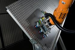
In the face of global competition, fabricators are looking for new ways to lower per-piece costs. So what about automation? Robotic automation can be an attractive option because of the well-known efficiency improvements realized in other metalworking and industrial applications where robots replaced manual operations. Robotic press brakes may offer higher productivity and better profitability—much of which is achieved by running the press brake lights-out at top speed (see Figure 1). In some cases, robotic press brakes can reduce per-piece costs by almost half.
Still, robotic press brakes aren’t for every application. With constant pressure to extract time and money from every process, many companies have few resources available to research all possibilities. They tend to focus on the attractive per-piece cost without exploring other creative solutions.
Robotic press brakes can be more than twice the cost of certain manual systems, depending on machine configurations. Those considering a robotic press brake often experience sticker shock. It takes a significant investment to get a robotic cell up and running. But if you can overcome the sticker shock, you can take a step back and consider the costs and benefits.
Initial Shocks
If you’ve survived that No. 1 sticker shock—the system cost—you can make the commitment to proceed. Your system utilization should be high enough to realize a suitable return on that initial investment within an acceptable timeframe.
Now for sticker shock No. 2: To run a part for the first time, setup costs on a robotic brake can be up to 10 times more expensive than an initial setup on a manual brake. Much planning and programming time is required to produce a single part. In a fluid world with many unknown variables, the tenfold-plus increase in upfront setup costs for each part can be the deal killer for press brake automation. Scrap comes into play here too. Although an automated system essentially eliminates scrap resulting from operator error, setup scrap skyrockets. On the initial setup, the entire system must be debugged—and this can include going through each bend at each station, one by one. It is not unusual to scrap hundreds of blanks during the initial setup.
Here’s sticker shock No. 3. Before you can enjoy the benefits of low per-piece cost, another upfront setup cost comes into play: the cost of executing each batch. The batch execution cost for each part varies. Depending on the application, the batch execution cost on a robotic press brake can be almost double that of a manual brake.
How can this be, you ask? Well, duplicate what a press brake operator does: Pick up a blank, bend it in the press brake, put it down. On the surface, the act of bending sheet metal seems so simple, but in fact it’s one of the most nuanced operations in the fabrication shop. An automated system needs a few more steps, because it’s not smart enough to find blanks by itself, and not accurate enough to reference those blanks either.
A robotic press brake cell has numerous components, and this adds to planning and layout costs. Even a small automated system for piece parts that weigh less than 35 pounds requires more than 500 square feet of floor space. Such systems require the press brake and robot, of course, but they also need a fencing cage for safety, a system entrance, incoming pallet station, a rack for additional robot grippers, a double-blank detection station, a squaring table, bending tools, racks for additional tools, a regrip station, an outgoing pallet station, and a system exit.
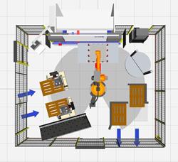
Figure 1: A robotic cell can make a bending operation extremely productive, but only for the right application.
On the other hand, a stand-alone press brake with a typical part weight capacity of more than 500 lbs. requires as little as 100 sq. ft. The only fixed-in-position element is the press brake itself. The tool rack may be moved around as needed, and work-in-process may be shared with other processes. Overall, a manual brake operation is fluid and flexible.
Offline programming can reduce downtime at the press brake, both for robotic and manual systems. This does, however, require office space, computer hardware, IT support, software, and trained support personnel. Other recurring costs may include hardware upgrades, software upgrades, and maintenance fees.
Using offline bending software with a robotic system, technicians can add new parts, select bending sequences, and generate press brake and robot programs. They create new part programs and then store them for downloading to the brake and robot. The floor technician then makes the initial run, tweaks the program as required, and then stores it in the workcell library, ready for production.
All the same benefits apply equally to stand-alone press brakes. The only difference is that knowledge, training, technical support, and programming time are less, because only one component—the bending itself—has to be considered. Offline programming is also much more widely available for standalone brakes. Robotic systems require software that integrates programming for not only the brake itself, but also the robot and other material handling elements.
Safety Considerations
Surrounding the robotic press brake system are guards firmly fixed in position. Light curtains or laser beam guards may offer more flexibility because there is no visible barrier. However, an inadvertent interruption of the beam will stop the process. Many safety codes require a manual reset to ensure the intruder has left the protection zone. Light guards also add more to the initial system cost.
For the stand-alone option, barrier guards are built into many new machines, and integrated laser light guards protect the pinch point when the brake is cycling.
Material Handling
To deliver blanks to a robotic cell requires forethought. Blanks can enter the system one by one or all at once, but people are blocked from entering the cell during automatic production. Part conveyors may be used, but these may sacrifice flexibility for productivity. Many times shops transport sheets via overhead cranes or forklifts. Bottlenecks also can occur if blanks arrive before they are needed. The stand-alone press brake, of course, has no fixed or formal system entrance. Blanks enter from any direction, and the operator can retrieve blanks when necessary.
Robot cells also use a rough-in locating device. The location of the part or stack of parts must be delivered within the tolerance of the pickup process. The operator carefully places the blanks against stops on the locating device. Flexibility suffers here, too, because this component usually is manually set up for each part. For a stand-alone system, the blanks are dropped anywhere in the area of the press brake.
When forming is completed, the robot can place finished parts in a bucket, or it may stack or nest them, and this requires manual planning and programming. Blanks can exit the system one by one or all at once. Part conveyors can increase productivity here as well, but as before, they make the system less flexible. Often finished parts are removed with overhead cranes or forklifts. Bottlenecks can occur here too. The transporter needs to keep returning to the cell to unload or move parts or shut down the system.
The Payload
Robot payload capacities have increased dramatically in recent years, and motion perimeters have become huge. Of course, larger capabilities require more floor space. A robot’s working range can increase by mounting it to a swing arm or carrier track. Careful planning is necessary here because a later upgrade can be expensive.
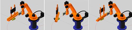
Figure 2: Because the part shape changes during bending, a robot may have to use a regripping station between bends.
Heavy parts may seem attractive automation candidates because of the manual material handling problems associated with the weight, but in many cases, volumes are just not high enough to justify a system with a high payload capacity. On a stand-alone system, the operator handles the parts, although heavy parts may require two operators as well as an overhead crane. The press brake itself—including its tonnage capacity and available tooling—is the limiting factor.
Getting a Grip
In most applications, the robot gripper is the single most critical component of the entire system. It is the primary interface between the industrial robot and the part. Many fabricators already enjoy the productivity of automated loading and unloading on their laser cutting and punching machines. When the blank size changes, these systems simply activate a different group of suction cups. At the press brake, however, part geometry changes with each bend. To handle a single part, the gripper must be configured to fit each step through the process. The same skill set required for chess comes into play when configuring grippers.
Grippers often are customized for each application. The gripper itself is very basic technology, but coordinating all the necessary elements of a gripper system isn’t so basic. Clamps, magnets, and vacuum cups must be configured to fit the part shape throughout the entire process, bend by bend, from flat to finish. Some clever automation approaches combine gripper configurations to fit part families. Automated gripper exchanges may also be used, depending on the batch sizes.
In some applications, a magazine of grippers may be used if it is impossible to design a gripper to fit all parts in a particular system. Also, as the part changes shape, sometimes the grippers need to reposition (see Figure 2).
Workpiece Detection and Referencing
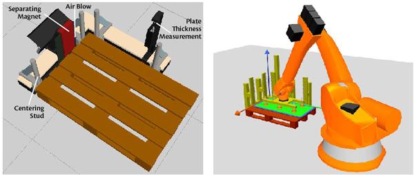
Robotic systems use magnet fanners, air knives, and edge peelers to separate single sheets from a stack. They require double-blank detectors to identify multiple blanks and, if necessary, stop the process (see Figure 3).
A squaring table ensures the robot always has the sheet properly oriented for processing (see Figure 4). Often a gravity part-blank alignment table is used. This is tilted so that gravity can help locate the blank properly. Once the part begins to take shape, tool clearances for up and down flanges and regripping locations must be exactly known. A precision locating device references the blank position. Some such devices include sensors that can stop the process if a blank does not comply. On a stand-alone press brake, if additional referencing is required, the locating system can be integrated with the standard backgauge.
Automated systems require only minimal modifications to the standard press brake. For instance, sensors in backgauge stops are added to tell the system that the blank is in the bend position. Sometimes formed angle sensing feeds back to the controller; if the formed part is out of tolerance, the controller stops the process.
More advanced systems have adaptive, in-proc-ess control over the bend angle. In-process gauging also can be implemented, with robots checking angles periodically and responding to material variation. Still, such adaptive systems actually are more common on stand-alone press brakes, because these machines usually handle a larger variety of parts.
Both automated and manual systems use standard, precision-ground tools, and most applications are air-bent. In lieu of adaptive control, though, an automated setup may use bottom bending if all bend angles are 90 degrees.
It may not be possible in some applications to design a tool to fit all parts, so a magazine of tools is used. The size of the magazine can vary greatly, and deciding whether to change tools manually or automatically again depends on batch sizes.
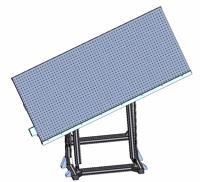
Figure 4: A squaring table ensures the robot always has the sheet properly oriented for processing.
Why Robotic Press Brakes Work
For the right applications an automated press brake can indeed work wonders. So what makes a good application for robotic bending? Without adequate volumes, automation won’t make sense. And one challenge remains: predictability. Will your customers consistently order these products? You can never know for sure, and this is one big reason that the fabrication industry hasn’t adopted robotic bending en masse. But if the orders are indeed consistent, a robotic press brake can help drive productivity and profits.
Robotic press brakes nearly eliminate scrap during production. As mentioned, though, setup scrap in robotic bending can be significant. In a manual setup, scrap is entirely operator-dependent. Note that new controllers with graphic simulation and other tools can help reduce that scrap.
These days robots are extremely reliable, even in harsh environments. Downtime usually occurs because of how elements are integrated, not because of an individual system component. If a system is installed and set up correctly, the robotic press brake can be an extremely reliable system.
Throughput is another obvious benefit. An automated system delivers consistent output. It can run unattended through lunch, breaks, off hours, and at night. Note that actual bending occurs at about the same speed as on a manual system, as does material handling. And the setup time actually can be shorter on a modern stand-alone press brake. Still, if set up properly, robotic press brakes keep running.
In fact, a manual press brake can sit idle for a significant portion of each shift. This is why, when weighing the pros and cons, shops often derate operator material handling speed by 80 percent to account for that unavoidable variability. Robots do not take breaks. They don’t get fatigued, get sick, have bad days, or file worker comp claims. Though just like people, they aren’t perfect. These days, if a robot goes down, the system can page you at night or on weekends and holidays.
Another benefit: Robots can be ideal for handling large, difficult-to-handle workpieces. Still, they are not the only way to reduce handling challenges. In a manually operated press brake, material handling devices such as part lifting tables and cranes can help reduce operator fatigue (see Figure 5).
Choose Wisely
The decision whether to automate or not isn’t easy. If you are constantly changing out press tooling; if you do prototype work; or if you have difficulty making your parts because of tooling, material, or process issues, press brake automation may not be the right path.
But for the right application, a robotic press brake can help a shop become a lot more productive. The robot may produce parts for a steady order that provides a consistent revenue stream—a beneficial complement to relatively unpredictable high-mix, low-volume work that flows through the rest of many shop floors.
Robots don’t make skilled-labor problems go away. Many shops have a difficult time finding workers of all skill levels, including those who perform mundane load and unload tasks, which a robot cell requires. And a robotic press brake still requires skilled personnel to run it. Even the best software in the world needs programmers with extensive knowledge of part production.
It boils down to productivity. Part quality, production scheduling, workforce management, and safety all can be handled effectively in ways that don’t necessarily require press brake automation. But an operator can work only so long without a break. If a worker forms the same part or part family time and time again, a robot probably could do it more effectively. But if order quantity and frequency are unpredictable, the story changes: The cost of changeovers and lengthy initial setups probably will outweigh any per-piece cost savings.
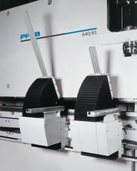
Figure 5: Material handling devices, like this part lifting table, can help reduce operator injury and fatigue.
About the Publication
subscribe now

The Fabricator is North America's leading magazine for the metal forming and fabricating industry. The magazine delivers the news, technical articles, and case histories that enable fabricators to do their jobs more efficiently. The Fabricator has served the industry since 1970.
start your free subscription- Stay connected from anywhere

Easily access valuable industry resources now with full access to the digital edition of The Fabricator.

Easily access valuable industry resources now with full access to the digital edition of The Welder.

Easily access valuable industry resources now with full access to the digital edition of The Tube and Pipe Journal.

Easily access valuable industry resources now with full access to the digital edition of The Fabricator en Español.
- Podcasting

In this episode of The Fabricator Podcast, Caleb Chamberlain, co-founder and CEO of OSH Cut, discusses his company’s...


